NordicTrack Grt490 English Manual - Page 11
Cable Assembly
 |
View all NordicTrack Grt490 manuals
Add to My Manuals
Save this manual to your list of manuals |
Page 11 highlights
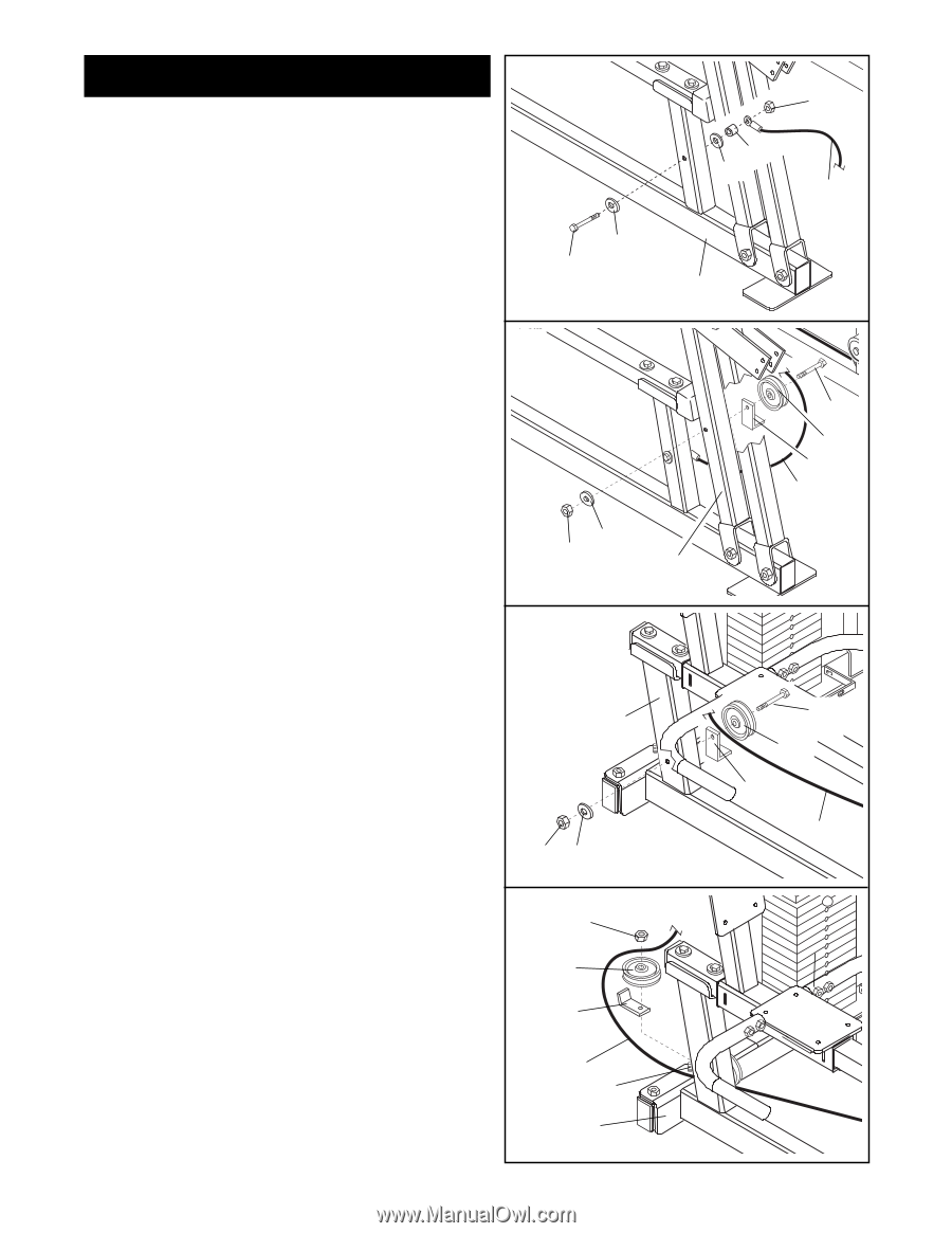
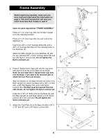
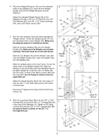
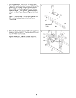
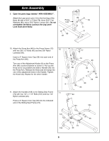
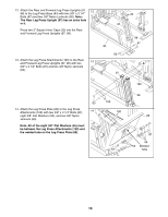
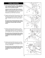
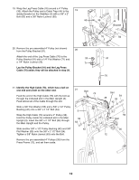
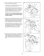
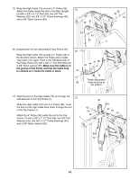
Cable Assembly 15 15. Open the parts bags labeled "CABLE ASSEMBLY" and "4 PULLEYS." Refer to the Cable Diagram on page 21 as you assemble the cables. Identify the Leg Press Cable (76) by referring to page 21. Attach the Leg Press Cable to the indicated hole in the Leg Press Base (84) with a 3/8" x 3" Bolt (45), two 3/8" Flat Washers (55), a 5/8" x 1/4" Bushing (90), and a 3/8" Nylon Jamnut (63). 55 45 63 90 55 76 84 16. Wrap the Leg Press Cable (76) up around a 4" Pulley 16 (35). Attach the Pulley and a Cable Trap (44) to the Rear Press Upright (97) with a 3/8" x 3 3/4" Bolt (92), a 3/8" Flat Washer (55), and a 3/8" Nylon Locknut (50). Be sure that the Leg Press Cable (76) is routed in the direction shown, and that the Cable Trap (44) is positioned to hold the Cable in the pulley groove. 55 50 97 92 35 44 76 17. Wrap the Leg Press Cable (76) under a 4" Pulley 17 (35). Attach the Pulley and a Cable Trap (44) to the Leg Press Base (84) with a 3/8" x 3 3/4" Bolt (92), a 3/8" Flat Washer (55), and a 3/8" Nylon Locknut (50). Be sure that the Leg Press Cable (76) is routed in the direction shown, and that the Cable Trap (44) 84 is positioned to hold the Cable in the pulley groove. 18. Wrap the Leg Press Cable (76) around a 4" Pulley (35). Attach the Pulley and a Cable Trap (44) to the 3/8" x 5" Carriage Bolt (82) in the Stabilizer (5) with a 3/8" Nylon Locknut (50). Be sure that the Leg Press Cable (76) is routed in the direction shown, and that the Cable Trap (44) is positioned to hold the Cable in the pulley groove. 50 55 18 50 35 44 76 82 5 92 35 44 76 11
-
 1
1 -
2
-
3
-
4
-
5
-
 6
6 -
 7
7 -
 8
8 -
 9
9 -
 10
10 -
 11
11 -
 12
12 -
 13
13 -
 14
14 -
 15
15 -
 16
16 -
17
-
18
-
19
-
20
-
21
-
22
-
23
-
24
-
25
-
26
-
27
-
28
-
29
-
30
-
31
-
32
-
33
 |
 |