NordicTrack Grt490 English Manual - Page 13
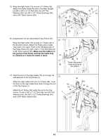
Wrap the High Cable 73 around another 4 Pulley
 |
View all NordicTrack Grt490 manuals
Add to My Manuals
Save this manual to your list of manuals |
Page 13 highlights
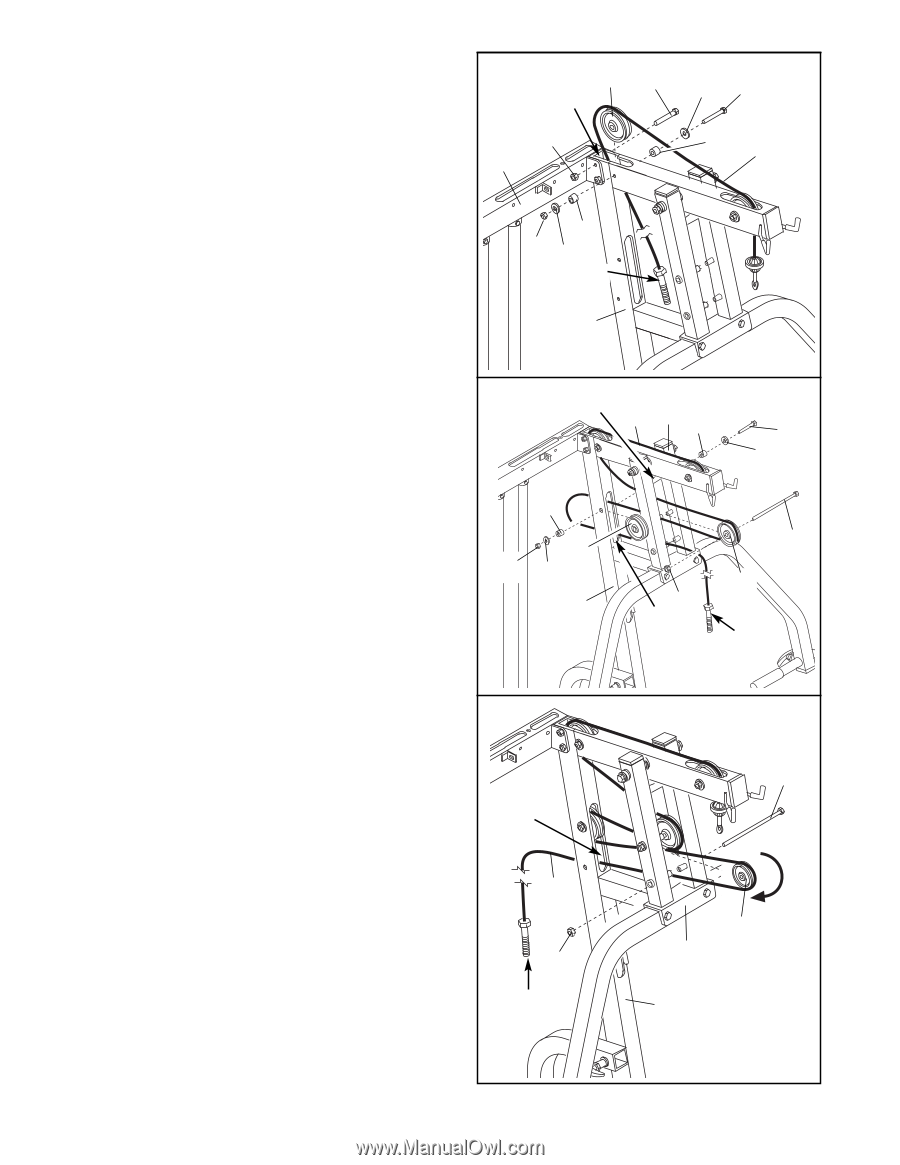
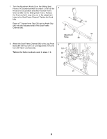
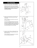
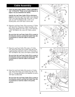
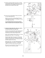
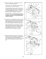
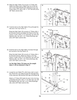
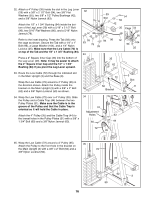
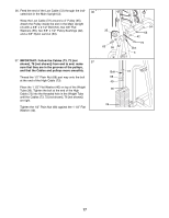
22. Remove the upper 3/8" x 3" Bolt (45) from the Top Frame (1) and the Main Upright (3). Feed the bolt on the High Cable (73) down through the indicated slot in the Main Upright (3). Wrap the High Cable (73) around a 4" Pulley (35) in the direction shown. Attach the Pulley inside the slot in the Main Upright (3) with a 3/8" x 2 1/2" Bolt (54), two 3/8" Flat Washers (55), two 5/8" x 1/2" Pulley Bushings (42), and a 3/8" Nylon Jamnut (63). Re-insert the 3/8" x 3" Bolt (45) and secure it with a 3/8" Nylon Locknut (50). Note: The Cable (73) must be seated in the groove of the Pulley (35) before the Bolt is attached. 22 35 45 Slot 50 1 42 63 55 Bolt 3 55 54 42 73 23. Feed the bolt on the High Cable (73) under the welded tube on the Press Frame (12) as shown. Wrap the High Cable around a 4" Pulley (35) in the direction shown. Attach the Pulley to the Press Frame with a 3/8" x 8 1/2" Bolt (59) and a 3/8" Nylon Locknut (50). 23 Welded Tube 73 12 42 Wrap the High Cable (73) around another 4" Pulley (35). Attach the Pulley inside the indicated slot in the Main Upright (3) with a 3/8" x 2 1/2" Bolt (54), two 3/8" Flat Washers (55), two 5/8" x 1/2" Pulley Bushings (42), and a 3/8" Nylon Jamnut (63). 42 35 63 55 55 50 Slot 54 55 59 35 Bolt 24. Wrap the High Cable (73) around a 4" Pulley (35) in 24 the direction shown. Feed the bolt on the High Cable back through the slot in the Main Upright (3) as shown. Attach the Pulley to the Press Frame (12) with a 3/8" x 8 1/2" Bolt (59) and a 3/8" Nylon Locknut 59 (50). Slot 73 50 Bolt 35 12 3 13
-
 1
1 -
2
-
3
-
4
-
5
-
6
-
7
-
 8
8 -
 9
9 -
 10
10 -
 11
11 -
 12
12 -
 13
13 -
 14
14 -
 15
15 -
 16
16 -
 17
17 -
 18
18 -
19
-
20
-
21
-
22
-
23
-
24
-
25
-
26
-
27
-
28
-
29
-
30
-
31
-
32
-
33
 |
 |