NordicTrack Grt490 English Manual - Page 9
Arm Assembly
 |
View all NordicTrack Grt490 manuals
Add to My Manuals
Save this manual to your list of manuals |
Page 9 highlights
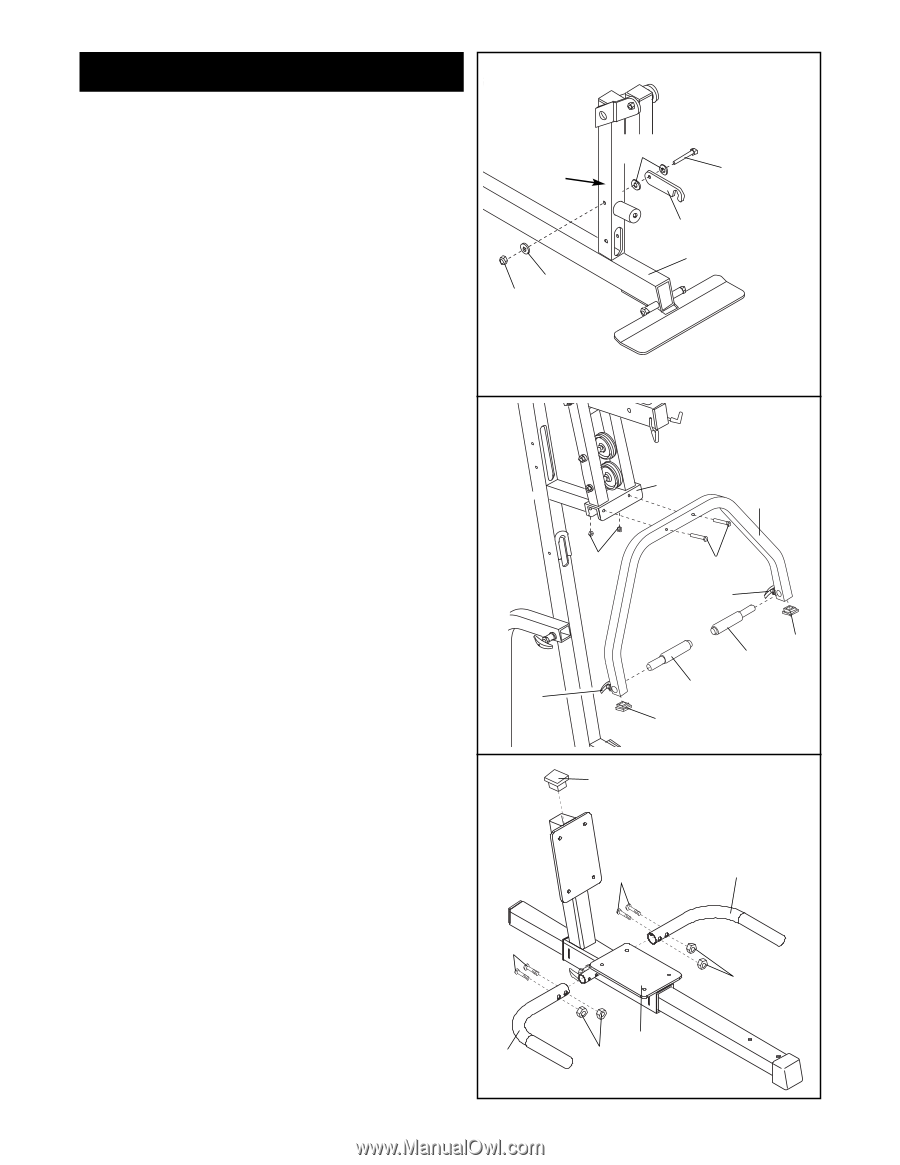
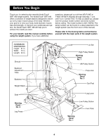
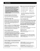
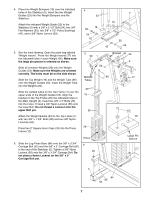
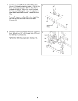
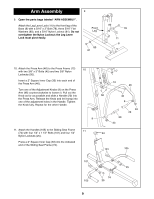
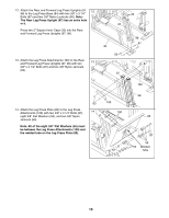
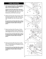
Arm Assembly 9 9. Open the parts bags labeled "ARM ASSEMBLY". Attach the Leg Lever Lock (11) to the front leg of the Base (8) with a 5/16" x 3" Bolt (78), three 5/16" Flat Washers (80), and a 5/16" Nylon Locknut (81). Do not overtighten the Nylon Locknut; the Leg Lever Lock must pivot easily. Front Leg 80 81 80 78 11 8 10. Attach the Press Arm (46) to the Press Frame (12) 10 with two 3/8" x 3" Bolts (45) and two 3/8" Nylon Locknuts (50). Insert a 2" Square Inner Cap (33) into each end of the Press Arm (46). Turn one of the Adjustment Knobs (9) on the Press Arm (46) counterclockwise to loosen it. Pull out the Knob as far as possible and slide a Handle (20) into the Press Arm. Release the Knob and let it snap into one of the adjustment holes in the Handle. Tighten the Knob fully. Repeat for the other Handle. 9 11. Attach the Handles (105) to the Sliding Seat Frame 11 (74) with four 1/4" x 1 1/2" Bolts (101) and four 1/4" Nylon Locknuts (25). Press a 2" Square Inner Cap (33) into the indicated end of the Sliding Seat Frame (74). 12 46 50 45 9 20 33 33 20 33 101 105 101 25 74 105 25 9
-
 1
1 -
2
-
3
-
 4
4 -
 5
5 -
 6
6 -
 7
7 -
 8
8 -
 9
9 -
 10
10 -
 11
11 -
 12
12 -
 13
13 -
 14
14 -
15
-
16
-
17
-
18
-
19
-
20
-
21
-
22
-
23
-
24
-
25
-
26
-
27
-
28
-
29
-
30
-
31
-
32
-
33
 |
 |