NordicTrack Grt490 English Manual - Page 16
Wrap the Low Cable 72 over a 4 Pulley 35. Slide
 |
View all NordicTrack Grt490 manuals
Add to My Manuals
Save this manual to your list of manuals |
Page 16 highlights
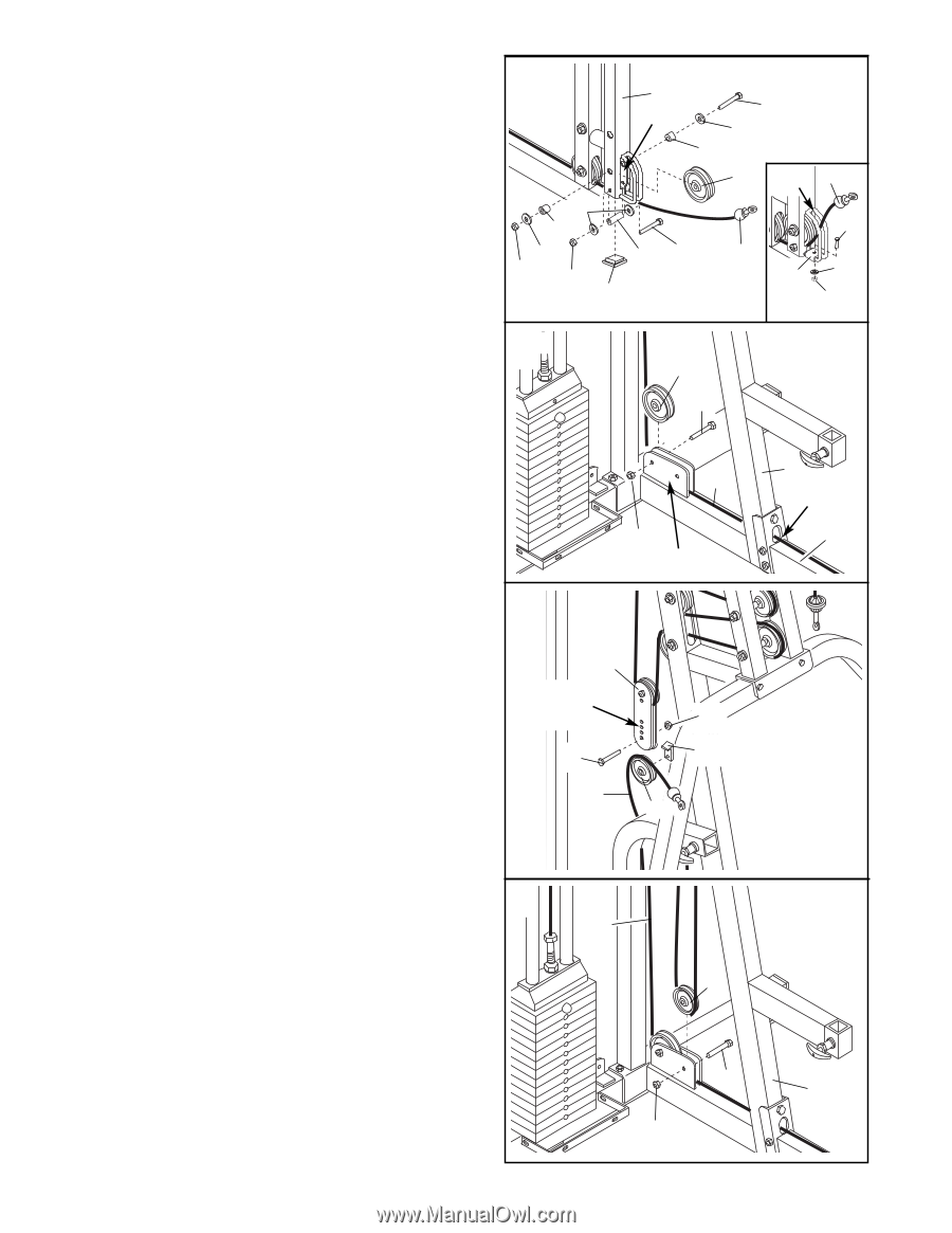
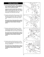
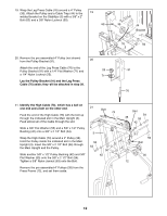
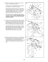
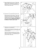
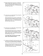
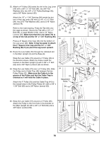
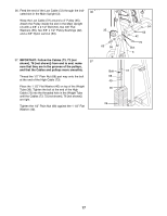
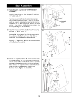
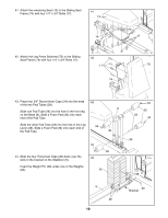
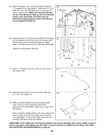
32. Attach a 4" Pulley (35) inside the slot in the Leg Lever (29) with a 3/8" x 2 1/2" Bolt (54), two 3/8" Flat Washers (55), two 5/8" x 1/2" Pulley Bushings (42), and a 3/8" Nylon Jamnut (63). Attach the 1/2" x 1 3/4" Bushing (94) inside the bottom of the Leg Lever (29) with a 5/16" x 2 1/2" Bolt (96), two 5/16" Flat Washers (80), and a 5/16" Nylon Jamnut (79). Refer to the inset drawing. Press the Tab (93) onto the cage as shown. Secure the Tab with a 1/4" x 1" Bolt (95), a Large Washer (104), and a 1/4" Nylon Locknut (25). Make sure that the Low Cable (72) is on top of the Tab and the 1/2" x 1 3/4" Bushing (94). Press a 2" Square Inner Cap (33) into the bottom of the Leg Lever (29). Note: It may be easier to attach the 2" Square Inner Cap and the 1/2" x 1 3/4" Bushing (94) if you pivot the Leg Lever upward. 32 80 42 55 63 79 33 33 29 Slot 54 55 42 35 Cage 72 94 96 95 72 93 104 25 35 62 33. Route the Low Cable (72) through the indicated slot in the Main Upright (3) and the Base (8). Wrap the Low Cable (72) around a 4" Pulley (35) in the direction shown. Attach the Pulley inside the bracket on the Main Upright (3) with a 3/8" x 2" Bolt (62) and a 3/8" Nylon Locknut (50) as shown. 34. Wrap the Low Cable (72) over a 4" Pulley (35). Slide the Pulley and a Cable Trap (44) between the two Pulley Plates (31). Make sure the Cable is in the groove of the Pulley and that the Cable Trap is oriented so it will hold the Cable in place. Attach the 4" Pulley (35) and the Cable Trap (44) to the lowest holes in the Pulley Plates (31) with a 3/8" x 1 3/4" Bolt (60) and a 3/8" Nylon Jamnut (63). 72 50 Bracket 34 31 Adjustment Holes 63 60 44 3 Slot 8 72 35 35. Wrap the Low Cable (72) around a 4" Pulley (35). 35 Attach the Pulley to the front hole in the bracket on the Main Upright (3) with a 3/8" x 2" Bolt (62) and a 72 3/8" Nylon Locknut (50). 35 62 3 50 16
-
 1
1 -
2
-
3
-
4
-
5
-
6
-
7
-
8
-
9
-
10
-
 11
11 -
 12
12 -
 13
13 -
 14
14 -
 15
15 -
 16
16 -
 17
17 -
 18
18 -
 19
19 -
 20
20 -
 21
21 -
22
-
23
-
24
-
25
-
26
-
27
-
28
-
29
-
30
-
31
-
32
-
33
 |
 |