NordicTrack Grt490 English Manual - Page 7
Carriage Bolt yet.
 |
View all NordicTrack Grt490 manuals
Add to My Manuals
Save this manual to your list of manuals |
Page 7 highlights
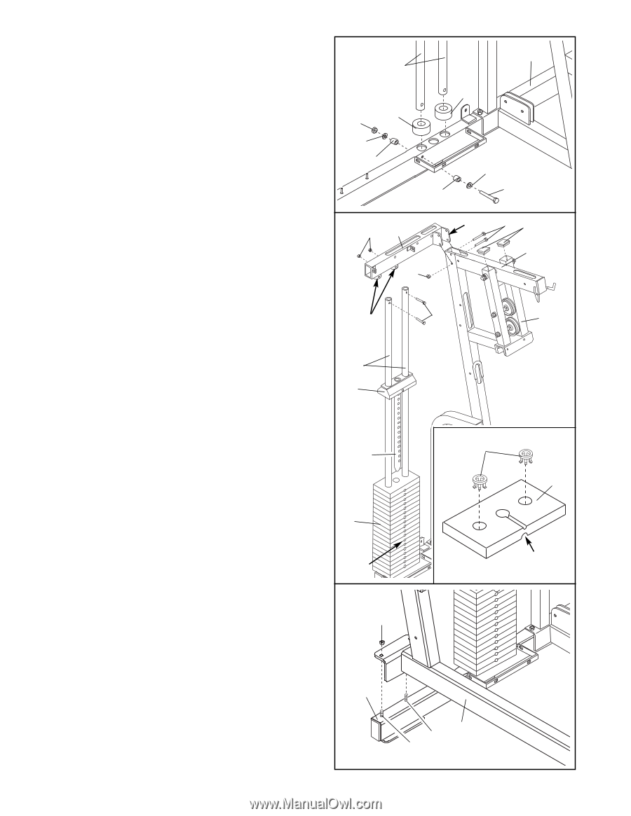
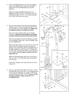
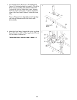
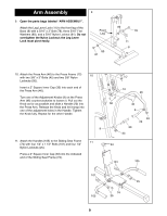
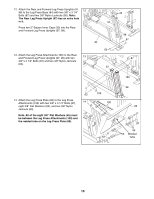
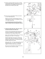
4. Place two Weight Bumpers (19) over the indicated holes in the Stabilizer (5). Insert the two Weight Guides (23) into the Weight Bumpers and the Stabilizer. Attach the indicated Weight Guide (23) to the Stabilizer (5) with a 3/8" x 2 1/2" Bolt (54), two 3/8" Flat Washers (55), two 5/8" x 1/2" Pulley Bushings (42), and a 3/8" Nylon Jamnut (63). 4 23 19 63 55 42 5 19 55 42 54 5. See the inset drawing. Open the parts bag labeled "Weight Inserts". Press two Weight Inserts (77) into the indicated holes in each Weight (26). Make sure the large pin groove is oriented as shown. Slide all nineteen Weights (26) onto the Weight Guides (23). Make sure the Weights are oriented correctly. The holes must be on the side shown. Slide the Top Weight (16) and the Weight Tube (36) onto the Weight Guides (23). Insert the Weight Tube into the Weights (26). Slide the welded tubes on the Top Frame (1) over the upper ends of the Weight Guides (23). Align the bracket on the Top Frame with the indicated holes in the Main Upright (3). Insert two 3/8" x 3" Bolts (45) into the holes. Thread a 3/8" Nylon Locknut (50) onto the lower Bolt. Do not thread a Locknut onto the upper Bolt yet. Attach the Weight Guides (23) to the Top Frame (1) with two 3/8" x 1 3/4" Bolts (60) and two 3/8" Nylon Locknuts (50). Press two 2" Square Inner Caps (33) into the Press Frame (12). 6. Slide the Leg Press Base (84) onto the 3/8" x 3 3/4" Carriage Bolt (52) and the 3/8" x 5" Carriage Bolt (82) in the end of the Stabilizer (5). Tighten a 3/8" Nylon Locknut (50) onto the 3/8" x 3 3/4" Carriage Bolt. Do not place a Nylon Locknut on the 3/8" x 5" Carriage Bolt yet. 5 50 1 50 Bracket 45 33 3 Welded 60 12 Tubes 23 16 36 26 Holes 6 50 77 26 Large Pin Groove 5 7 84 82 52
-
 1
1 -
 2
2 -
 3
3 -
 4
4 -
 5
5 -
 6
6 -
 7
7 -
 8
8 -
 9
9 -
 10
10 -
 11
11 -
 12
12 -
13
-
14
-
15
-
16
-
17
-
18
-
19
-
20
-
21
-
22
-
23
-
24
-
25
-
26
-
27
-
28
-
29
-
30
-
31
-
32
-
33
 |
 |