Pioneer DJM-700 Owner's Manual
Pioneer DJM-700 Manual
 |
UPC - 012562860862
View all Pioneer DJM-700 manuals
Add to My Manuals
Save this manual to your list of manuals |
Pioneer DJM-700 manual content summary:
- Pioneer DJM-700 | Owner's Manual - Page 1
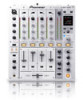
DJ MIXER DJM-700-S DJM-700-K Operating Instructions - Pioneer DJM-700 | Owner's Manual - Page 2
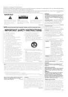
risk of electric shock to persons. CAUTION: TO PREVENT THE RISK OF ELECTRIC SHOCK, DO NOT REMOVE COVER (OR BACK). NO USER-SERVICEABLE PARTS INSIDE. REFER SERVICING TO QUALIFIED SERVICE PERSONNEL. The exclamation point within an equilateral triangle is intended to alert the user to the presence of - Pioneer DJM-700 | Owner's Manual - Page 3
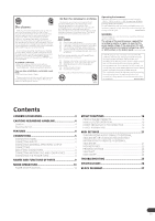
FUNCTIONS OF PARTS 9 MIXER OPERATIONS 13 FADER START FUNCTION 14 EFFECT FUNCTIONS 16 PRODUCING BEAT EFFECTS 18 MANUAL FILTER OPERATION 19 EFFECT FREQUENCY FILTER OPERATION 19 EFFECT PARAMETERS 20 MIDI SETTINGS 21 SYNCHRONIZING AUDIO SIGNALS TO EXTERNAL SEQUENCER, OR USING DJM-700-S/DJM-700 - Pioneer DJM-700 | Owner's Manual - Page 4
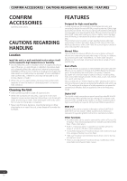
DJM-700-S/ DJM-700-K can be output in MIDI signal format, allowing a component supporting MIDI control to be controlled via MIDI. Other functions • A control cable can be used to connect the unit to a Pioneer DJ CD player, thus allowing playback to be linked to operation of the fader ("fader start - Pioneer DJM-700 | Owner's Manual - Page 5
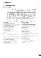
level input connectors. Use to connect a DJ CD player or other line level output component. 7 CONTROL connectors Ø3.5 mm mini-connector. Use to connect to the control connector of a Pioneer DJ CD player. When the connectors are connected, the DJM-700-S/DJM-700-K's fader can be used to perform start - Pioneer DJM-700 | Owner's Manual - Page 6
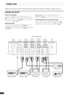
connections. CONNECTING INPUTS Pioneer DJ CD players The audio output connectors of a DJ-type CD player can be connected to the CD input connectors (channel 1 or 2), or to the LINE input connectors (channel 1) of the DJM-700-S/DJM-700-K. Connect the control cord to the CONTROL jack, and set - Pioneer DJM-700 | Owner's Manual - Page 7
L+R channels. Booth monitor output Unbalanced output supporting RCA-type plug. The sound volume for this output is controlled by the BOOTH MONITOR LEVEL dial, independently of the master output level setting. Recording output These are output connectors for recording, supporting RCA plugs. Digital - Pioneer DJM-700 | Owner's Manual - Page 8
MIDI connectors. CONNECTING MICROPHONE AND HEADPHONES Microphone A microphone with XLR-type plug can be connected to the MIC 1 connector on the Operation Panel (upper) . The MIC 2 jack on the connection panel can be used 12 +12 MIC TALK OFF ON OVER FADER START CH-1 CH-2 CONNECTING THE POWER - Pioneer DJM-700 | Owner's Manual - Page 9
: Microphone sound is output; when sound is input to a connected microphone, the TALK OVER function operates and all sound other than that from the microphone is attenuated by 20 dB. • When not using the TALK OVER function, it is recommended to set the switch to the [OFF] or [ON] position. 8 Channel - Pioneer DJM-700 | Owner's Manual - Page 10
) Use to adjust the master output level. (adjustable range: -∞ to 0 dB) The master output is the sum combination of the sound from channels set to [THRU] with the CROSS FADER ASSIGN switch; the signal passed through the cross fader; and the signals from microphone 1 and microphone 2 (if the effect - Pioneer DJM-700 | Owner's Manual - Page 11
MIDI On MIDIOff 2 Channel select display section Lights position selected by effect channel selector. 3 Parameter display section AUTO/TAP: [AUTO] lights when the BPM measuring mode is set to AUTO, and [TAP] lights when the BPM measuring mode is set to manual (TAP). BPM counter display (3 digits - Pioneer DJM-700 | Owner's Manual - Page 12
PARTS the two ends, no indicators light. Effect selector DELAY Effect display Effect name DELAY Parameter display Beat display /1 TRANS TRANS 10 16 000 500 ms 1/16 1/8 1/4 1/2 1/1 2/1 4/1 8/1 16/1 FILTER FILTER 10 32 000 2 000 ms 1/4 1/2 1/1 2/1 4/1 8/1 16/1 32/1 64/1 FLANGER - Pioneer DJM-700 | Owner's Manual - Page 13
BOOTH MONITOR LEVEL dial to adjust the sound volume. • The BOOTH MONITOR LEVEL dial can be used to adjust the sound volume independently of the MASTER LEVEL dial. [Headphones Output] 1 Use the HEADPHONES CUE buttons (channels 1 to 4, MASTER, EFFECTS) to select the source. • The selected HEADPHONES - Pioneer DJM-700 | Owner's Manual - Page 14
. • This setting produces equal curve effects for both sides A and B. FADER START FUNCTION By connecting the optional Pioneer DJ CD Player control cable, the channel fader and cross fader can be used to start CD playback. When the mixer's channel fader lever or cross fader lever are moved, the CD - Pioneer DJM-700 | Owner's Manual - Page 15
MIXER OPERATIONS [Using the Cross Fader to Start Playback] FADER START 1 1, 2 CROSS FADER 2 ASSIGN A / THRU / B 35 1 Press the FADER START button for the channel (1, 2) connected to the CD player you wish to control. • The button for the selected channel lights. 2 Set the CROSS FADER ASSIGN switch - Pioneer DJM-700 | Owner's Manual - Page 16
with the manual filter or effect frequency filter depending on the positioning of the FREQUENCY dial. Additionally, by combining beat effects with the manual filter or effect frequency filter, a wide range of effects can be created. TYPES OF BEAT EFFECTS 1 DELAY (One repeat sound) This function - Pioneer DJM-700 | Owner's Manual - Page 17
1/4, 1/2, 1/1, 2/1, 4/1, 8/1, 16/1 beats, and plays them repeatedly while continuously lowering their pitch/key. Example Effect ON Original 1/1 roll Repeat 11 REVERSE ROLL Records sounds at 1/16, 1/8, 1/4, 1/2, 1/1, 2/1, 4/1, 8/1, 16/1 beats and repeats them but in reverse order. Example Original - Pioneer DJM-700 | Owner's Manual - Page 18
MIDI BPM % mS Effect Name: DELAY Effect Channel Select: CH 1 BPM value: 120 BPM Parameter 1: 500 ms 2 3 TIME LEVEL/DEPTH 5 ON/OFF Beat multiple: 1/1 Beat effects allow the instant setting of effect this case, press the TAP button and input the beat manually. [Using the TAP Button for Manual BPM - Pioneer DJM-700 | Owner's Manual - Page 19
FREQUENCY dial. The output sounds of the manual effecter become the input sounds for the beat effect. • When the beat effect type is set to ROLL, REVERSE ROLL, UP ROLL, or DOWN ROLL, the beat effect's output sound becomes the input sound for the manual effecter. 1 Press the FILTER button so that it - Pioneer DJM-700 | Owner's Manual - Page 20
EFFECT FUNCTIONS EFFECT PARAMETERS Beat Effect (*1) Name 1 DELAY 2 ECHO (*2) 3 TRANS 4 FILTER 5 FLANGER Beat effect monitor is turned ON, if the selected channel's sound is not output to the master output, the effect sound will not be heard. (*2) When effect is disabled (OFF), the effect sound - Pioneer DJM-700 | Owner's Manual - Page 21
USING DJM-700-S/DJM-700-K INFORMATION TO OPERATE AN EXTERNAL SEQUENCER 1 Use a commercially available MIDI cable to connect the DJM-700-S/DJM-700-K's MIDI OUT connector to the MIDI sequencer's MIDI IN connector. • Set the MIDI sequencer's synch mode to "Slave". • MIDI sequencers that do not support - Pioneer DJM-700 | Owner's Manual - Page 22
MIDI MESSAGES Category CH1 CH2 CH3 CH4 CROSS FADER FADER CURVE MASTER BOOTH FILTER Switch Name HI MID LOW CUE FADER CF ASSIGN HI MID LOW CUE FADER CF ASSIGN HI MID LOW CUE FADER CF ASSIGN HI MID LOW CUE FADER CF ASSIGN CROSS FADER CH CURVE CROSS CURVE MASTER LEVEL BALANCE CUE MONITOR FILTER - Pioneer DJM-700 | Owner's Manual - Page 23
TAP TAP CUE EFFECT KIND CH SELECT TIME MIC (FADER START) (HEAD PHONES) MIDI LEVEL/DEPTH EFFECT ON/OFF HI LOW FADER START 1 FADER START 2 CHANGE" below. Bn 0D MSB Bn 2D LSB PARAMETER 1 value; FLANGER, PHASER, FILTER, CRUSH changed to 1/2 value; minus values are converted to positive. Bn 5B dd - Pioneer DJM-700 | Owner's Manual - Page 24
SNAPSHOT Once the DJM-700-S/DJM-700-K is setup with parameters for a given purpose, that set of parameters can be recorded as a snapshot. When snapshot of the current status is recorded, all messages for control change and program change are transmitted. Hold the MIDI START/STOP button depressed - Pioneer DJM-700 | Owner's Manual - Page 25
. • Only the rear panel CONTROL jack is connected to the CD player. • Set the FADER START button to ON. • Use a control cable to connect the CONTROL jacks of mixer and CD player. • Connect both the CONTROL jacks and analog input connectors. Effects don't work. • Effect channel selecter setting is - Pioneer DJM-700 | Owner's Manual - Page 26
, or if you wish to purchase replacement parts, operating instructions, service manuals, or accessories, please call the number shown below. 800 - 782 - 7210 Please do not ship your product to Pioneer without first calling the Customer Support Division at the above listed number for assistance - Pioneer DJM-700 | Owner's Manual - Page 27
BLOCK DIAGRAM BLOCK DIAGRAM 27 En - Pioneer DJM-700 | Owner's Manual - Page 28
CORPORATION 1-1, Shin-ogura, Saiwai-ku, Kawasaki-shi, Kanagawa 212-0031, Japan PIONEER ELECTRONICS (USA) INC. P.O. BOX 1540, Long Beach, California 90801-1540, U.S.A. TEL: (800) 421-1404 PIONEER ELECTRONICS OF CANADA, INC. Industrial Products Department: 300 Allstate Parkway, Markham, Ontario
-
 1
1 -
 2
2 -
 3
3 -
 4
4 -
 5
5 -
 6
6 -
 7
7 -
8
-
9
-
10
-
11
-
12
-
13
-
14
-
15
-
16
-
17
-
18
-
19
-
20
-
21
-
22
-
23
-
24
-
25
-
26
-
27
-
28
 |
 |
Operating Instructions
DJ MIXER
DJM-700-S
DJM-700-K