Pioneer DJM-700 Owner's Manual - Page 12
Beat display Maximum, value - effects
 |
UPC - 012562860862
View all Pioneer DJM-700 manuals
Add to My Manuals
Save this manual to your list of manuals |
Page 12 highlights
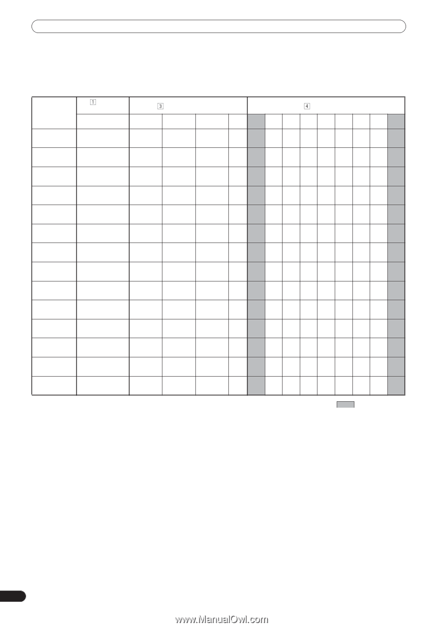
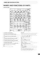
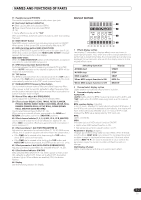
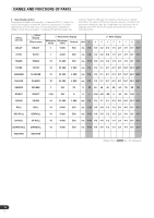
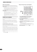
NAMES AND FUNCTIONS OF PARTS 4 Beat display section Displays the location of parameter 1 relative to BPM (1/1 beat). The lower row is lighted constantly. When the parameter 1 location approaches a threshold value, the corresponding indicator is lighted. When the parameter 1 is between threshold values, the indicator flashes. Although the display includes seven actual indicators, the values of the two ends can also be considered to represent indicators, with the result that nine positions can be logically assumed. When the values are at the two ends, no indicators light. Effect selector DELAY Effect display Effect name DELAY Parameter display Beat display Minimum Maximum value value Default Unit ➀ ➁ ➂ ➃ ➄ ➅ ➆ ➇ ➈ 1 4 000 500 ms 1/8 1/4 1/2 3/4 1/1 2/1 4/1 8/1 16/1 ECHO ECHO 1 4 000 500 ms 1/8 1/4 1/2 3/4 1/1 2/1 4/1 8/1 16/1 TRANS TRANS 10 16 000 500 ms 1/16 1/8 1/4 1/2 1/1 2/1 4/1 8/1 16/1 FILTER FILTER 10 32 000 2 000 ms 1/4 1/2 1/1 2/1 4/1 8/1 16/1 32/1 64/1 FLANGER FLANGER 10 32 000 2 000 ms 1/4 1/2 1/1 2/1 4/1 8/1 16/1 32/1 64/1 PHASER PHASER 10 32 000 2 000 ms 1/4 1/2 1/1 2/1 4/1 8/1 16/1 32/1 64/1 REVERB REVERB 1 100 50 % 10 20 30 40 50 60 70 80 90 ROBOT ROBOT -100 100 0 % - -100 -66 -50 0 26 50 100 - CRUSH CRUSH 10 32 000 2 000 ms 1/4 1/2 1/1 2/1 4/1 8/1 16/1 32/1 64/1 ROLL ROLL 10 4 000 500 ms 1/16 1/8 1/4 1/2 1/1 2/1 4/1 8/1 16/1 REV ROLL REVROLL 10 4 000 500 ms 1/16 1/8 1/4 1/2 1/1 2/1 4/1 8/1 16/1 UP ROLL UP ROLL 10 4 000 500 ms 1/16 1/8 1/4 1/2 1/1 2/1 4/1 8/1 16/1 DOWN ROLL DWNROLL 10 4 000 500 ms 1/16 1/8 1/4 1/2 1/1 2/1 4/1 8/1 16/1 SND/RTN SND/RTN Shaded items are not displayed. 12 En
-
 1
1 -
2
-
3
-
4
-
5
-
6
-
 7
7 -
 8
8 -
 9
9 -
 10
10 -
 11
11 -
 12
12 -
 13
13 -
 14
14 -
 15
15 -
 16
16 -
 17
17 -
18
-
19
-
20
-
21
-
22
-
23
-
24
-
25
-
26
-
27
-
28
 |
 |