Pioneer DJM-700 Owner's Manual - Page 5
Connections - midi
 |
UPC - 012562860862
View all Pioneer DJM-700 manuals
Add to My Manuals
Save this manual to your list of manuals |
Page 5 highlights
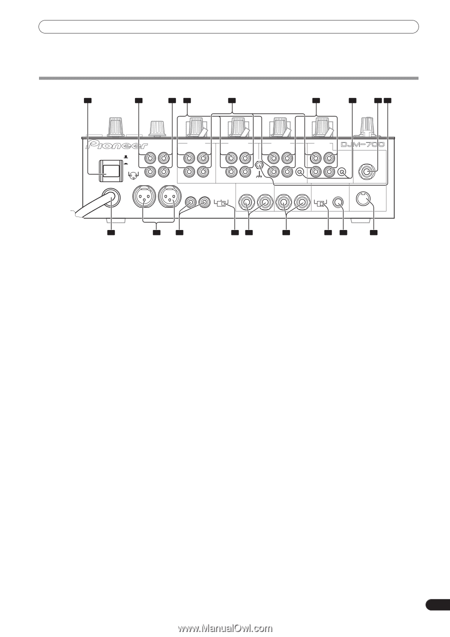
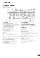
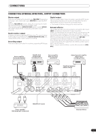
CONNECTIONS CONNECTIONS CONNECTION PANEL 1 2 34 5 6 7 89 POWER OFF ON BOOTH REC L 1 GND 2 HOT R 3 COLD R MASTER1 L CH-4 PHONO LINE L CH-3 PHONO LINE L CH-2 PHONO CD L CH-1 LINE CD L CONTROL CONTROL MIC 2 R MASTER2 MASTER RL ATT. -6dB -3dB 0dB R SIGNAL GND SEND R L(MONO) R R RETURN R L(MONO) DIGITAL OUT fs(Hz) 48k 96k MIDI OUT 18 17 16 1 POWER switch 2 BOOTH monitor output connectors RCA-type booth monitor output jack. The sound level from these connectors is controlled independently by the BOOTH MONITOR LEVEL dial, regardless of the position of the MASTER LEVEL dial. 3 Recording output connectors (REC) RCA type output connectors for recording. 4 PHONO input connectors RCA type phono level (MM cartridge) input connectors. Do not use for inputting line level signals. 5 LINE input connectors RCA type line level input connectors. Use to connect a cassette deck or other line level output component. 6 CD input connectors RCA type line level input connectors. Use to connect a DJ CD player or other line level output component. 7 CONTROL connectors Ø3.5 mm mini-connector. Use to connect to the control connector of a Pioneer DJ CD player. When the connectors are connected, the DJM-700-S/DJM-700-K's fader can be used to perform start/stop on the DJ CD player. 8 Two microphone input jacks (MIC 2) Connect microphones equipped with phone-type plugs. 9 Signal grounding terminals (SIGNAL GND) Reduces noise when connecting an analog turntable. 10 MIDI OUT connector DIN type output connector. Use to connect to other MIDI component (see P. 21). 15 14 13 12 11 10 11 DIGITAL OUT connector RCA type digital coaxial output connector. Master audio digital output. 12 Sampling frequency selector switch (fs 48 k/96 k) Use to set the sampling frequency of the digital output to 96 kHz/ 24-bit format or 48 kHz/24-bit format. • Turn power off before changing this switch position. 13 RETURN connectors Ø6.3 mm phone-type input connectors. Use to connect to the output connectors of external effectors or similar components. When the L channel only is connected, the L channel input is simultaneously input to the R channel. 14 SEND output connectors Ø6.3 mm phone-type output connectors. Use to connect to the input connectors of external effectors or other similar components. When the L channel only is connected, a L+R monaural signal is output. 15 Master output attenuator switch (MASTER ATT) Use to attenuate the level of the master 1 and master 2 outputs. Attenuation can be set to 0 dB, -3 dB, or -6 dB. 16 MASTER 2 output connectors RCA type unbalanced output. 17 MASTER 1 output connectors XLR type (male) balanced output. • When using a cord with RCA-type plug, users are recommended to connect the plug directly to the MASTER 2 connectors without using an XLR/RCA converter plug. 18 Power cord Connect to ordinary AC outlet. 5 En
-
 1
1 -
 2
2 -
 3
3 -
 4
4 -
 5
5 -
 6
6 -
 7
7 -
 8
8 -
 9
9 -
 10
10 -
 11
11 -
12
-
13
-
14
-
15
-
16
-
17
-
18
-
19
-
20
-
21
-
22
-
23
-
24
-
25
-
26
-
27
-
28
 |
 |