ProForm Pro C22 Instruction Manual - Page 9
Make sure
 |
View all ProForm Pro C22 manuals
Add to My Manuals
Save this manual to your list of manuals |
Page 9 highlights
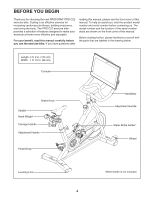
6. Note: You can attach your own pedals if desired. 6 Identify the Right Pedal (16). Using the included wrench, firmly tighten the Right Pedal clockwise into the Right Crank Arm (18). Firmly tighten the Left Pedal (17) counter- clockwise into the Left Crank Arm (not shown). IMPORTANT: You must turn the Left 18 Pedal counterclockwise to attach it. 16 17 7. Have a second person hold the Handlebar (4) near the Frame (1). 7 Next, locate the wire tie (A) in the Frame (1). Tie the wire tie to the Handlebar Wire (90) in the Handlebar (4). Then, pull the lower end of the wire tie until the Handlebar Wire is routed B through the Frame. Untie and discard the wire tie. 4 Tip: See the upper inset drawing to learn how to operate the Adjustment Handle (14). Next, locate the Adjustment Handle (14) on the front of the Frame (1). Pull the Adjustment Handle outward, and insert the Handlebar (4) into the Frame. Next, move the Handlebar (4) downward and release the Adjustment Handle (14) into the indicated adjustment hole (B). Then, tighten the Adjustment Handle four turns. Make sure that the Adjustment Handle is firmly engaged in the adjustment hole. 90 1 14 A A C Then, pull the Adjustment Handle (14) outward, turn it so that it points downward as shown, and then release it. 1 See the lower inset drawing. Insert the Handlebar Wire (90) through the zip tie (C) on the Frame (1); do not connect the Handlebar Wire and do not tighten the zip tie yet. 90 Loosen handle Pull handle Adjust post Release handle Tighten handle Pull handle Turn handle down C 9
-
 1
1 -
2
-
3
-
 4
4 -
 5
5 -
 6
6 -
 7
7 -
 8
8 -
 9
9 -
 10
10 -
 11
11 -
 12
12 -
 13
13 -
 14
14 -
15
-
16
-
17
-
18
-
19
-
20
-
21
-
22
-
23
-
24
-
25
-
26
-
27
-
28
-
29
-
30
-
31
-
32
-
33
-
34
-
35
-
36
 |
 |
