Samsung SHR-5042 User Manual - Page 11
Real Panel Jacks
 |
View all Samsung SHR-5042 manuals
Add to My Manuals
Save this manual to your list of manuals |
Page 11 highlights
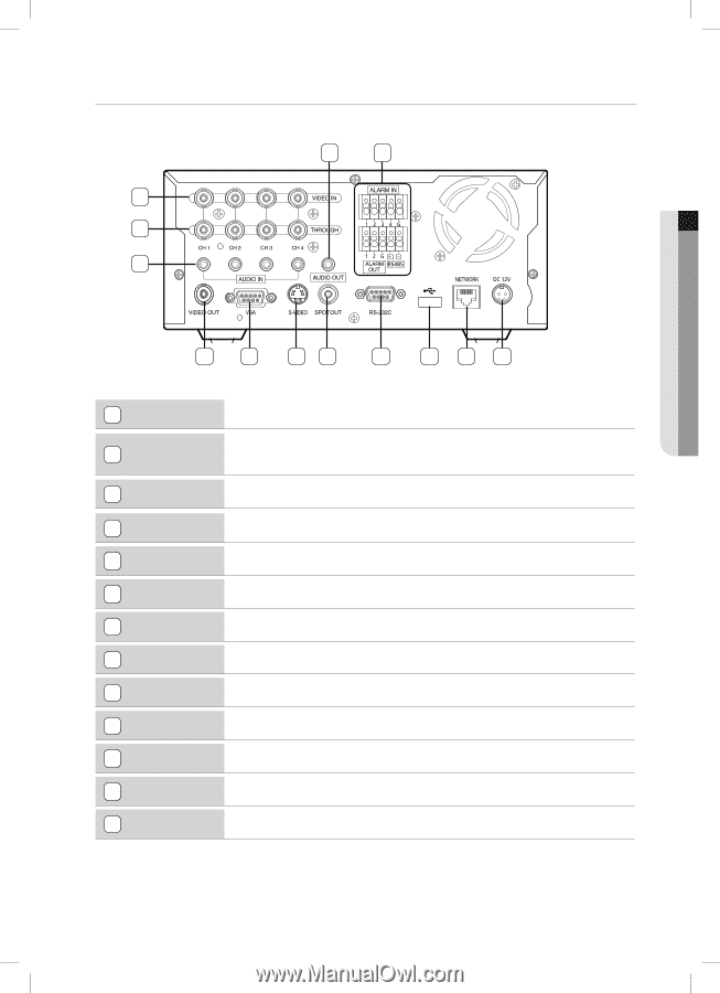
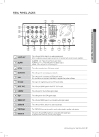
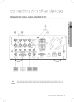
01 INTRODUCING YOUR REAL TIME DVR REAL PANEL JACKS 13 12 11 1 2 10 9 8 7 6 5 4 3 1 AUDIO OUT 2 ALARM 3 DC-IN 4 NETWORK 5 USB 6 RS-232C 7 SPOT OUT 8 S-VIDEO 9 VGA 10 VIDEO OUT 11 AUDIO IN 12 THROUGH 13 VIDEO-IN This is the port (RCA Jack) for an audio signal output. (When outputting an audio signal, please use the speaker with a built-in audio amplifier.) ALARM IN 1~4: This is the port for an alarm input. ALARM OUT 1~2: This is the port for an alarm output. RS485: This is the port for connecting PTZ. This is the connector for a 12V power socket. This is the port for connecting to a network. This is the port for connecting a USB type of device. It is used when you backup a video data or upgrade the system software. This is port for engineering use (no DVR functionality). This is the port (BNC-type) for the SPOT OUT output. This is the port for the S-Video signal output. This is the port for the VGA signal output. This is the port (BNC-type) for a composite audio signal output. This is the port (RCA Jack) for an audio signal input. The THROUGH port can be used to send a video signal to another video device. This port is the port (BNC-type) for a composite video signal input. It supports both the NTSC and PAL video signals. SHR-5042_Eng.indb 7 introducing your real time DVR_07 2007-06-08 1:23:53
-
 1
1 -
2
-
3
-
4
-
5
-
 6
6 -
 7
7 -
 8
8 -
 9
9 -
 10
10 -
 11
11 -
 12
12 -
 13
13 -
 14
14 -
 15
15 -
 16
16 -
17
-
18
-
19
-
20
-
21
-
22
-
23
-
24
-
25
-
26
-
27
-
28
-
29
-
30
-
31
-
32
-
33
-
34
-
35
-
36
-
37
-
38
-
39
-
40
-
41
-
42
-
43
-
44
-
45
-
46
-
47
-
48
-
49
-
50
-
51
-
52
-
53
-
54
-
55
-
56
-
57
-
58
-
59
-
60
-
61
-
62
-
63
-
64
-
65
-
66
-
67
-
68
-
69
-
70
-
71
-
72
-
73
-
74
-
75
-
76
-
77
-
78
 |
 |