Sharp XR-50S XR-55S XR-55X Operation Manual - Page 48
Signal Adjustment SIG-ADJ Menu
 |
View all Sharp XR-50S manuals
Add to My Manuals
Save this manual to your list of manuals |
Page 48 highlights
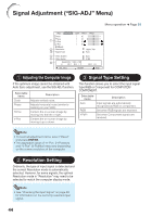
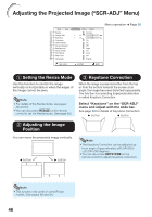
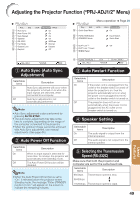
Signal Adjustment ("SIG-ADJ" Menu) Menu operation n Page 39 Pict. SIG-ADJ SCR PRJ1 PRJ2 Clock 0 Phase 0 1 H-Pos 0 V-Pos Reset 2 Resolution 3 Signal Type 0 1024 x 768 Auto 4 Video System 5 Video Setup 6 Signal Info : 1024 x 768 H 48.3 kHz / V Auto 0 IRE 60.0 Hz SEL./ADJ. ENTER END 1 Adjusting the Computer Image If the optimum image cannot be obtained with Auto Sync adjustment, use the SIG-ADJ function. Selectable items Clock Phase H-Pos V-Pos Description Adjusts vertical noise. Adjusts horizontal noise (similar to tracking on your VCR). Centers the on-screen image by moving it to the left or right. Centers the on-screen image by moving it up or down. 3 Signal Type Setting This function allows you to select the input signal type RGB or Component for COMPUTER/ COMPONENT. Selectable items Auto RGB YPbPr Description Input signals are automatically recognized as RGB or component. Set when RGB signals are received. Set when Component signals are received. Note • To reset all adjustment items, select "Reset" and press ENTER. • The adjustable range of "H-Pos" (H-Position) and "V-Pos" (V-Position) may vary depending on the screen resolution of the computer. 2 Resolution Setting Ordinarily, the type of input signal is detected and the correct Resolution mode is automatically selected. However, for some signals, the optimal Resolution mode in "Resolution" may need to be selected to match the computer display mode. Note • See "Checking the Input Signal" on page 45 for information on the currently selected input signal. 44
-
 1
1 -
2
-
3
-
4
-
5
-
6
-
7
-
8
-
9
-
10
-
11
-
12
-
13
-
14
-
15
-
16
-
17
-
18
-
19
-
20
-
21
-
22
-
23
-
24
-
25
-
26
-
27
-
28
-
29
-
30
-
31
-
32
-
33
-
34
-
35
-
36
-
37
-
38
-
39
-
40
-
41
-
42
-
 43
43 -
 44
44 -
 45
45 -
 46
46 -
 47
47 -
 48
48 -
 49
49 -
 50
50 -
 51
51 -
 52
52 -
 53
53 -
54
-
55
-
56
-
57
-
58
-
59
-
60
-
61
-
62
-
63
-
64
-
65
-
66
-
67
-
68
-
69
-
70
-
71
-
72
-
73
-
74
-
75
-
76
-
77
-
78
 |
 |
