Sharp XR-50S XR-55S XR-55X Operation Manual - Page 63
Connecting Pin Assignments
 |
View all Sharp XR-50S manuals
Add to My Manuals
Save this manual to your list of manuals |
Page 63 highlights
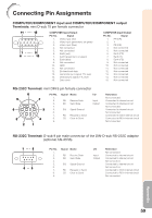
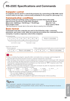
Connecting Pin Assignments COMPUTER/COMPONENT input and COMPUTER/COMPONENT output Terminals: mini D-sub 15 pin female connector 11 15 COMPUTER Input/Output COMPUTER Input/Output Pin No. Signal Pin No. Signal 1. Video input (red) 1. PR (CR) 2. Video input (green/sync on green) 2. Y 3. Video input (blue) 3. PB (CB) 4. Not connected 4. Not connected 1 5 6 10 5. Not connected 6. Earth (red) 7. Earth (green/sync on green) 5. Not connected 6. Earth (PR) 7. Earth (Y) 8. Earth (blue) 8. Earth (PB) 9. Not connected 9. Not connected 10. GND 10. Not connected 11. Not connected 11. Not connected 12. Bi-directional data 12. Not connected 13. Horizontal sync signal: TTL level 13. Not connected 14. Vertical sync signal: TTL level 14. Not connected 15. Data clock 15. Not connected RS-232C Terminal: mini DIN 9 pin female connector 9 6 5 8 2 1 7 3 4 Pin No. 1. 2. 3. 4. 5. 6. 7. 8. 9. Signal Name RD Receive Data SD Send Data SG Signal Ground RS Request to Send CS Clear to Send I/O Input Output Reference Not connected Connected to internal circuit Connected to internal circuit Not connected Connected to internal circuit Not connected Connected to CS in internal circuit Connected to RS in internal circuit Not connected RS-232C Terminal: D-sub 9 pin male connector of the DIN-D-sub RS-232C adaptor (optional AN-A1RS) 1 5 69 Pin No. 1. 2. 3. 4. 5. 6. 7. 8. 9. Signal Name RD Receive Data SD Send Data SG Signal Ground RS Request to Send CS Clear to Send I/O Input Output Reference Not connected Connected to internal circuit Connected to internal circuit Not connected Connected to internal circuit Not connected Connected to CS in internal circuit Connected to RS in internal circuit Not connected Appendix 59
-
 1
1 -
2
-
3
-
4
-
5
-
6
-
7
-
8
-
9
-
10
-
11
-
12
-
13
-
14
-
15
-
16
-
17
-
18
-
19
-
20
-
21
-
22
-
23
-
24
-
25
-
26
-
27
-
28
-
29
-
30
-
31
-
32
-
33
-
34
-
35
-
36
-
37
-
38
-
39
-
40
-
41
-
42
-
43
-
44
-
45
-
46
-
47
-
48
-
49
-
50
-
51
-
52
-
53
-
54
-
55
-
56
-
57
-
 58
58 -
 59
59 -
 60
60 -
 61
61 -
 62
62 -
 63
63 -
 64
64 -
 65
65 -
 66
66 -
 67
67 -
 68
68 -
69
-
70
-
71
-
72
-
73
-
74
-
75
-
76
-
77
-
78
 |
 |
