Sony HDWS280 Product Manual (Operation Manual 1st Edition (Revised 5)) - Page 17
Audio data
 |
View all Sony HDWS280 manuals
Add to My Manuals
Save this manual to your list of manuals |
Page 17 highlights
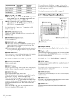
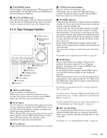
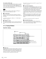
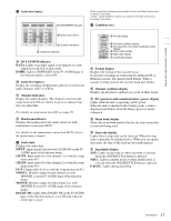
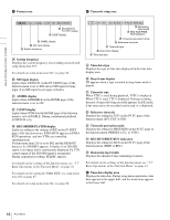
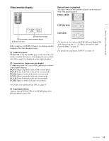
Chapter 2 Names and Functions of Parts b Audio level meter EMPH EMPH EMPH EMPH 0 0 -10 -10 -20 -20 -30 -30 -40 -40 1 23 4 A DATA/EMPH indicator B Audio level meters C Channel indicators D Headroom indicator A DATA/EMPH indicator DATA: Lights if an audio signal is recognized as a data signal in record, E-E or play mode. EMPH: Lights if EMPHASIS on the P3 AUDIO page of the function menu is set to ON. B Audio level meters Display the recording and playback audio levels of the four audio channels (CH-1 to CH-4). C Channel indicators Display the audio channels. The channels selected with setup menu item 826 are shown in green to indicate that they are adjustable. For details on setup menu item 826, see page 76. D Headroom indicator Displays the headroom for the audio circuit set with maintenance menu item M370. For details on the maintenance menu item M370 refer to the maintenance manual. c Audio data Displays the audio data. INPUT: Input signal selected with AUDIO IN on the P3 AUDIO page of the function menu. CH1 IN: Input audio level for channel 1 set with the setup menu item 834. CH2 IN: Input audio level for channel 2 set with the setup menu item 834. OUT: Output audio level set with the setup menu item 812. MONI L: Monitor output for left channel set with MONITR L on the P3 AUDIO page of the function menu. MONI R: Monitor output for right channel set with MONITR R on the P3 AUDIO page of the function menu. DOLBY NR: Lights when DOLBY NR on the P3 AUDIO page of the function menu is set to ON and when an oxide tape is used. Dolby noise reduction manufactured under license from Dolby Laboratories Licensing Corporation. "Dolby" and the double-D symbol are trademarks of Dolby Laboratories Licensing Corporation. d Condition area HD A Format display COND BANK 2 D-STOP P ROLL B Channel condition display C DC operation and remaining battery power display D Menu bank display E Stop code display F Jog/shuttle display A Format display Displays the format of the cassette in use. If you start recording on a Betacam SX, Betacam SP, or Betacam cassette, the cassette mark flashes. When a cassette is being ejected, the cassette mark also flashes. B Channel condition display Displays the playback condition on a scale of three levels. C DC operation and remaining battery power display Lights while the unit is operating on DC power. When the unit is operated with a battery pack, a slash is displayed and flashes when the battery power is nearly exhausted. D Menu bank display Shows the menu bank number that has the same menu data as currently being used. E Stop code display Lights when a stop code can be detected. When the stop code is detected, the display flashes. When you cue up the shot mark, the type of the cued-up shot mark appears. F Jog/shuttle display JOG: Lights in jog mode or when jog mode is selected when the JOG/SHUTTLE button is pressed. SHTL: Lights in shuttle mode or when shuttle mode is selected when the JOG/SHUTTLE button is pressed. P ROLL: Lights during prerolling. 17 Front Panel
-
 1
1 -
2
-
3
-
4
-
5
-
6
-
7
-
8
-
9
-
10
-
11
-
 12
12 -
 13
13 -
 14
14 -
 15
15 -
 16
16 -
 17
17 -
 18
18 -
 19
19 -
 20
20 -
 21
21 -
 22
22 -
23
-
24
-
25
-
26
-
27
-
28
-
29
-
30
-
31
-
32
-
33
-
34
-
35
-
36
-
37
-
38
-
39
-
40
-
41
-
42
-
43
-
44
-
45
-
46
-
47
-
48
-
49
-
50
-
51
-
52
-
53
-
54
-
55
-
56
-
57
-
58
-
59
-
60
-
61
-
62
-
63
-
64
-
65
-
66
-
67
-
68
-
69
-
70
-
71
-
72
-
73
-
74
-
75
-
76
-
77
-
78
-
79
-
80
-
81
-
82
-
83
-
84
-
85
-
86
-
87
-
88
-
89
-
90
-
91
-
92
-
93
-
94
 |
 |
