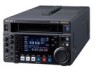
Sony HDWS280 Product Manual (Operation Manual 1st Edition (Revised 5)) - Page 68
Items 300 to 399: Settings for editing, 9PIN], number, Item name, Settings, ACCUR], ROUGH, MANU],
 |
View all Sony HDWS280 manuals
Add to My Manuals
Save this manual to your list of manuals |
Page 68 highlights
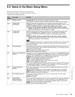
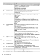
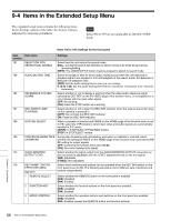
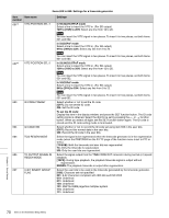
Item Item name number 214 REMOTE INTERFACE Settings Select a device which remotely controls this unit. [9PIN]: A device connected to the REMOTE 9P connector SDI:A device connected to the HD SDI connector a) Not applicable in 24PsF/23.98PsF mode Items 300 to 399: Settings for editing Item number 305 307 309 318 326 334 Item name SYNC GRADE AUTO-DELETION FOR INCONSISTENT DATA SERVO/AV REFERENCE SEL EDIT RETRY AUTOMATIC IN ENTRY AFTER AUTOEDIT EE REFERENCE CONTROL Settings When editing in phase-synchronized mode with menu item 004 set to ON, select the target phase synchronization accuracy. [ACCUR]: ±0 frame accuracy ROUGH: ±1 frame accuracy Select what happens when an erroneous edit point is set. [MANU]: A warning is given by flashing the DELETE indicator on the P5 EDIT page of the function menu. Delete an unnecessary edit point, or set it correctly. NEG&E: When inconsistent edit points are set, such as when an OUT point is before an IN point, or when too many edit points are specified, the previously set edit point is deleted. NEG: When inconsistent edit points are set, such as when an OUT point is before an IN point, the previously set edit point is deleted. When more edit points than necessary are specified, the DELETE indicator flashes to give a warning. Note Pressing the function button corresponding to an edit point to be deleted and the DELETE function button simultaneously deletes the edit point. If an erroneous edit point is set (the DELETE indicator is flashing), editing is not executed. Select the servo reference signal. [AUTO1]: During recording, the input video signal is used as the servo reference signal. During playback, the signal selected by OUT REF on the P2 VIDEO page of the function menu is used as the servo reference signal. If the signal selected by the OUT REF setting is not connected, an internal reference signal is used. AUTO2: When OUT REF on the P2 VIDEO page of the function menu is set to REF, and ASSEMBLE on the HOME page of the function menu is set to ON, the reference signal for video/audio signal processing is locked to the input video signal. EXT: The servo reference signal is forced to be an external reference video input. For two-VTR editing, set when this unit is used as the recorder. Selects the operation if the recorder was not synchronized in time. OFF: Editing is not carried out, and the unit stops. [ON]: The editing is automatically retried (up to twice). Select whether or not to automatically set the OUT point of the previous edit as the next IN point at the end of an automatic edit. [OFF]: No automatic setting R: Set recorder IN point automatically. R & P: Set recorder IN point automatically, and also player IN point in two-VTR editing. Sets the method to select the reference video signal in E-E mode. [NORMAL]: Select according to the table in "3-5 Setting Reference Video Signals" on page 27. INPUT: Select an input video signal in E-E mode. In other cases, Select according to the table in "3-5 Setting Reference Video Signals" on page 27. Chapter 9 Setup Menus 68 Items in the Extended Setup Menu
-
 1
1 -
2
-
3
-
4
-
5
-
6
-
7
-
8
-
9
-
10
-
11
-
12
-
13
-
14
-
15
-
16
-
17
-
18
-
19
-
20
-
21
-
22
-
23
-
24
-
25
-
26
-
27
-
28
-
29
-
30
-
31
-
32
-
33
-
34
-
35
-
36
-
37
-
38
-
39
-
40
-
41
-
42
-
43
-
44
-
45
-
46
-
47
-
48
-
49
-
50
-
51
-
52
-
53
-
54
-
55
-
56
-
57
-
58
-
59
-
60
-
61
-
62
-
 63
63 -
 64
64 -
 65
65 -
 66
66 -
 67
67 -
 68
68 -
 69
69 -
 70
70 -
 71
71 -
 72
72 -
 73
73 -
74
-
75
-
76
-
77
-
78
-
79
-
80
-
81
-
82
-
83
-
84
-
85
-
86
-
87
-
88
-
89
-
90
-
91
-
92
-
93
-
94
 |
 |