Sony PCV-J150 System Reference Manual (primary manual) - Page 51
location of pin 1 on the module and pin 1 on the socket.
 |
View all Sony PCV-J150 manuals
Add to My Manuals
Save this manual to your list of manuals |
Page 51 highlights
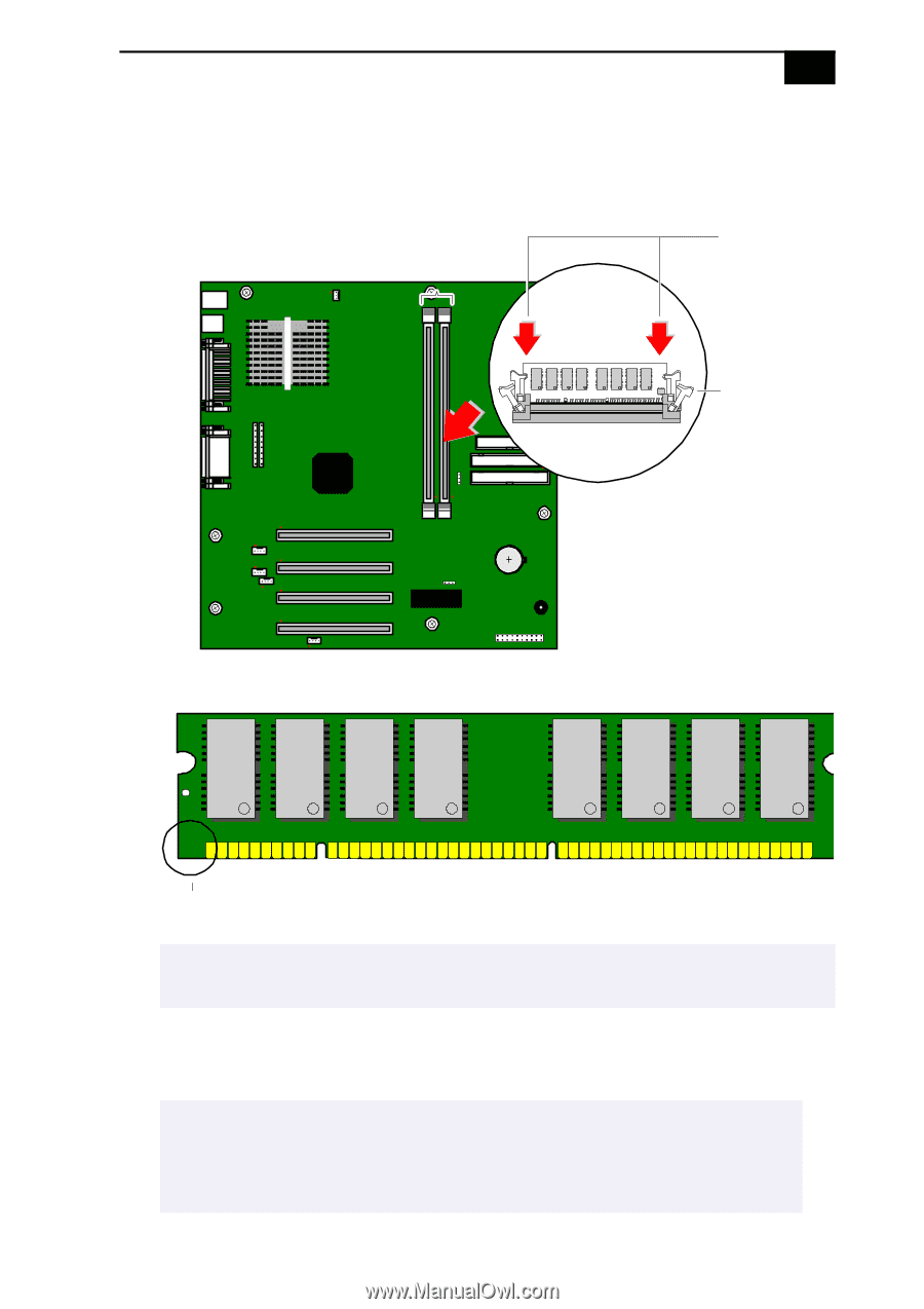
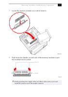
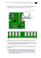
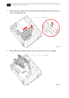
Removing, Installing, and Replacing Components 37 8 Align the memory module over the appropriate socket, noting the location of pin 1 on the module and pin 1 on the socket. Press down here Handles Memory module (DIMM) 1 9 Carefully but firmly insert the edge of the module into the socket. ✍ Gently push the power supply cables and ribbon cables aside as you slip your hands into the system to reach the module connector. 10 Press down firmly and evenly at both corners until the module is fully seated. ✍ When the module is fully seated, the handles on each side are straight up and locked into the slot on each side of the module. If the handles are not totally straight upright, continue to press down on each side of the module until the handles lock into place.
-
 1
1 -
2
-
3
-
4
-
5
-
6
-
7
-
8
-
9
-
10
-
11
-
12
-
13
-
14
-
15
-
16
-
17
-
18
-
19
-
20
-
21
-
22
-
23
-
24
-
25
-
26
-
27
-
28
-
29
-
30
-
31
-
32
-
33
-
34
-
35
-
36
-
37
-
38
-
39
-
40
-
41
-
42
-
43
-
44
-
45
-
 46
46 -
 47
47 -
 48
48 -
 49
49 -
 50
50 -
 51
51 -
 52
52 -
 53
53 -
 54
54 -
 55
55 -
 56
56 -
57
-
58
-
59
-
60
-
61
-
62
-
63
-
64
-
65
-
66
-
67
-
68
-
69
-
70
-
71
-
72
-
73
-
74
-
75
-
76
-
77
-
78
-
79
-
80
-
81
-
82
-
83
-
84
-
85
-
86
-
87
-
88
-
89
-
90
-
91
-
92
-
93
-
94
-
95
-
96
-
97
-
98
-
99
-
100
-
101
-
102
-
103
-
104
 |
 |