Sony PCV-J150 System Reference Manual (primary manual) - Page 59
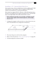
Heading1 - System Board
 |
View all Sony PCV-J150 manuals
Add to My Manuals
Save this manual to your list of manuals |
Page 59 highlights
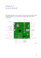
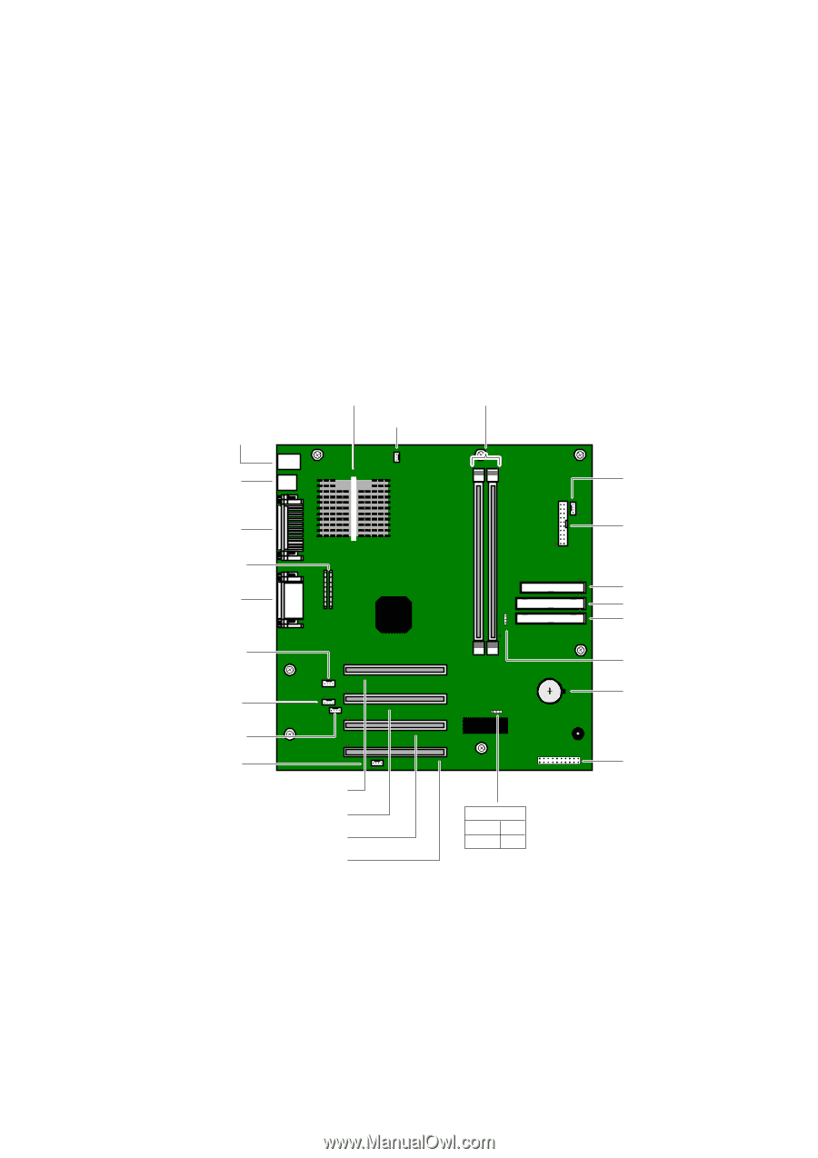
Chapter 4 System Board This chapter identifies each component on the system board and provides a detailed description of each connector, jumper, and switch on the system board. Keyboard, Mouse CPU CPU Fan Memory USB1/2/3 Power Supply Fan Parallel (top), i.Link, Monitor IEEE 1394 Header (not used) Serial (top) MicIn, Line In, Line Out Video (not used) CD-In (to CD-RW drive) Aux-In (not used) Wake-On-LAN (not used) PCI slot 4 PCI slot 3 PCI slot 2 PCI slot 1 CMOS Clear Normal 1-2 Clear 2-3 Power Supply Diskette Secondary IDE Primary IDE VIRQ Battery Front panel header OM04581.VS 47
-
 1
1 -
2
-
3
-
4
-
5
-
6
-
7
-
8
-
9
-
10
-
11
-
12
-
13
-
14
-
15
-
16
-
17
-
18
-
19
-
20
-
21
-
22
-
23
-
24
-
25
-
26
-
27
-
28
-
29
-
30
-
31
-
32
-
33
-
34
-
35
-
36
-
37
-
38
-
39
-
40
-
41
-
42
-
43
-
44
-
45
-
46
-
47
-
48
-
49
-
50
-
51
-
52
-
53
-
 54
54 -
 55
55 -
 56
56 -
 57
57 -
 58
58 -
 59
59 -
 60
60 -
 61
61 -
 62
62 -
 63
63 -
 64
64 -
65
-
66
-
67
-
68
-
69
-
70
-
71
-
72
-
73
-
74
-
75
-
76
-
77
-
78
-
79
-
80
-
81
-
82
-
83
-
84
-
85
-
86
-
87
-
88
-
89
-
90
-
91
-
92
-
93
-
94
-
95
-
96
-
97
-
98
-
99
-
100
-
101
-
102
-
103
-
104
 |
 |
47
Chapter 4
System Board
This chapter identifies each component on the system board and provides
a detailed description of each connector, jumper, and switch on the
system board.
CPU
Memory
Secondary IDE
Primary IDE
Battery
OM04581.VS
CPU Fan
Diskette
Front pane
l header
Seria
l (top)
MicIn, Line In, Line Out
Para
lle
l (top),
i.Link, Monitor
USB1/2/3
Power Supply Fan
Keyboard, Mouse
Aux-In (not used)
CD-In (to CD-RW drive)
Power Supply
PC
I slot 3
PC
I slot 4
PC
I slot 2
CMOS C
lear
C
lear
2-3
Norma
l 1-2
PC
I slot 1
VIRQ
Video (not used)
Wake-On-LAN (not used)
IEEE 1394 Header
(not used)