Sony PCV-J150 System Reference Manual (primary manual) - Page 67
Heading3 - PRINTER, i.LINK, and MONITOR Connectors, The PRINTER, i.LINK IEEE 1394
 |
View all Sony PCV-J150 manuals
Add to My Manuals
Save this manual to your list of manuals |
Page 67 highlights
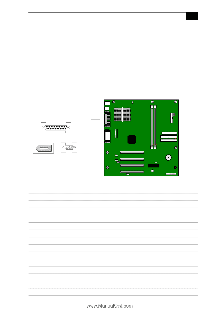
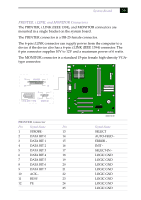
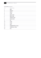
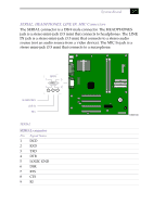
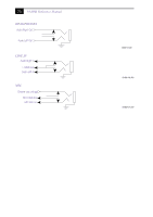
System Board 55 PRINTER, i.LINK, and MONITOR Connectors The PRINTER, i.LINK (IEEE 1394), and MONITOR connectors are mounted in a single bracket on the system board. The PRINTER connector is a DB-25 female connector. The 6-pin i.LINK connector can supply power from the computer to a device if the device also has a 6-pin i.LINK (IEEE 1394) connector. The 6-pin connector supplies 10V to 12V and a maximum power of 6 watts. The MONITOR connector is a standard 15-pin female high-density VGAtype connector. 13 PRINTER 1 25 14 5 1 15 11 i.LINK (IEEE 1394) MONITOR PRINTER connector Pin Signal Name Pin 1 STROBE - 13 2 DATA BIT 0 14 3 DATA BIT 1 15 4 DATA BIT 2 16 5 DATA BIT 3 17 6 DATA BIT 4 18 7 DATA BIT 5 19 8 DATA BIT 6 20 9 DATA BIT 7 21 10 ACK - 22 11 BUSY 23 12 PE 24 25 OM04701D.VSD Signal Name SELECT AUTO-FEED ERROR INIT SELECT-IN LOGIC GND LOGIC GND LOGIC GND LOGIC GND LOGIC GND LOGIC GND LOGIC GND LOGIC GND
-
 1
1 -
2
-
3
-
4
-
5
-
6
-
7
-
8
-
9
-
10
-
11
-
12
-
13
-
14
-
15
-
16
-
17
-
18
-
19
-
20
-
21
-
22
-
23
-
24
-
25
-
26
-
27
-
28
-
29
-
30
-
31
-
32
-
33
-
34
-
35
-
36
-
37
-
38
-
39
-
40
-
41
-
42
-
43
-
44
-
45
-
46
-
47
-
48
-
49
-
50
-
51
-
52
-
53
-
54
-
55
-
56
-
57
-
58
-
59
-
60
-
61
-
 62
62 -
 63
63 -
 64
64 -
 65
65 -
 66
66 -
 67
67 -
 68
68 -
 69
69 -
 70
70 -
 71
71 -
 72
72 -
73
-
74
-
75
-
76
-
77
-
78
-
79
-
80
-
81
-
82
-
83
-
84
-
85
-
86
-
87
-
88
-
89
-
90
-
91
-
92
-
93
-
94
-
95
-
96
-
97
-
98
-
99
-
100
-
101
-
102
-
103
-
104
 |
 |