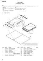
Sony PRS-505/SC Service Manual - Page 42
Sony PRS-505/SC - Portable Reader System Manual
 |
View all Sony PRS-505/SC manuals
Add to My Manuals
Save this manual to your list of manuals |
Page 42 highlights
PRS-505 Pin No. K5 K6, K7 K8 K9 K10 K11 K12 K13 K14 K15 L1, L2 L3, L4 L5, L6 L7 L8 L9 L10, L11 L12 L13 L14 L15 M1 M2 to M4 M5 M6 M7, M8 M9 M10 M11 M12 M13 M14 M15 N1, N2 N3 N4 N5, N6 N7, N8 N9 N10 N11, N12 N13 N14 N15 P1 P2 P3 to P6 P7, P8 P9, P10 Pin Name NVDD1 VSS NVDD1 VSS D1 BOOT2 TDI BIG_ENDIAN XRESET-OUT XTAL32K A10, A9 D17, D18 NVDD1 XCS5 D2 PA20 VSS POR VSS XTAL16M EXTAL32K D16 D15, D13, D10 XEB3 NVDD1 XCS4, XCS1 PA18 XRW VSS BOOT3 QVDD2 XRESET-IN EXTAL16M A8, A7 D12 XEB0 D9, D8 XCS3, XCS0 PA17 D0 DQM2,DQM0 SDCK0 TRISTATE XTRST D14 A1 A2 to A5 D6, D5 MA10, MA11 I/O Description - Power supply terminal (+2.9V) - Ground terminal - Power supply terminal (+2.9V) - Ground terminal I/O Two-way data bus with the memory stick duo/SD memory card controller, USB controller, NAND flash memory, SD-RAM and NOR flash memory I System boot mode select signal input terminal I Test data input terminal Not used I Not used O Reset signal output to the audio D/A converter, memory stick duo/SD memory card controller, USB controller, NAND flash memory and NOR flash memory O System clock output terminal (32.768 kHz) O Address signal output to the memory stick duo/SD memory card controller, SD-RAM and NOR flash memory I/O Two-way data bus with the SD-RAM - Power supply terminal (+2.9V) O Chip select signal output terminal I/O Two-way data bus with the memory stick duo/SD memory card controller, USB controller, NAND flash memory, SD-RAM and NOR flash memory O Not used - Ground terminal I Power on reset signal input from the sub CPU "H": reset - Ground terminal O System clock output terminal Not used I System clock input terminal (32.768 kHz) I/O Two-way data bus with the SD-RAM I/O Two-way data bus with the memory stick duo/SD memory card controller, USB controller, SD-RAM and NOR flash memory O Byte strobe signal output terminal Not used - Power supply terminal (+2.9V) O Chip select signal output terminal - Not used O Read/write enable signal output terminal - Ground terminal I System boot mode select signal input terminal - Power supply terminal (+1.9V) I Master reset signal input from the sub CPU "L": reset I System clock input terminal Not used O Address signal output to the memory stick duo/SD memory card controller, USB controller, SD-RAM and NOR flash memory I/O Two-way data bus with the memory stick duo/SD memory card controller, USB controller, SD-RAM and NOR flash memory O Byte strobe signal output terminal Not used I/O Two-way data bus with the memory stick duo/SD memory card controller, USB controller, SD-RAM and NOR flash memory O Chip select signal output terminal - Not used I/O Two-way data bus with the memory stick duo/SD memory card controller, USB controller, NAND flash memory, SD-RAM and NOR flash memory O Data enable signal output to the SD-RAM O Clock enable signal output to the SD-RAM I Not used I Test reset signal input terminal Not used I/O Two-way data bus with the memory stick duo/SD memory card controller, USB controller, SD-RAM and NOR flash memory O Address signal output to the memory stick duo/SD memory card controller, USB controller and NOR flash memory O Address signal output to the memory stick duo/SD memory card controller, USB controller, SD-RAM and NOR flash memory I/O Two-way data bus with the memory stick duo/SD memory card controller, USB controller, NAND flash memory, SD-RAM and NOR flash memory O Address signal output to the SD-RAM 42
-
 1
1 -
2
-
3
-
4
-
5
-
6
-
7
-
8
-
9
-
10
-
11
-
12
-
13
-
14
-
15
-
16
-
17
-
18
-
19
-
20
-
21
-
22
-
23
-
24
-
25
-
26
-
27
-
28
-
29
-
30
-
31
-
32
-
33
-
34
-
35
-
36
-
 37
37 -
 38
38 -
 39
39 -
 40
40 -
 41
41 -
 42
42 -
 43
43 -
 44
44 -
 45
45 -
 46
46 -
 47
47 -
48
-
49
-
50
-
51
-
52
-
53
-
54
-
55
-
56
-
57
-
58
-
59
-
60
-
61
-
62
-
63
-
64
-
65
-
66
-
67
-
68
-
69
-
70
-
71
-
72
-
73
-
74
 |
 |
