Weider 9025 Uk Manual - Page 7
Attach the Top Frame 6 to the Front and Rear
 |
View all Weider 9025 manuals
Add to My Manuals
Save this manual to your list of manuals |
Page 7 highlights
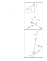
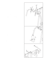
4. Insert two Weight Guides (5) into the Base (1). 4 Make sure that the holes are on the top. Slide two Weight Bumpers (44) onto the Weight Guides (5). Slide the nine Weights (16) onto the Weight Guides. Press the Weight Tube Bumper (17) into the Weight Tube (18). Insert the Weight Tube into the stack of Weights (16) as shown. Lubricate the indicated holes in the Top Weight (19) with grease. Slide the Top Weight onto the Weight Guides (5). Make sure the pin on the Weight Tube (18) rests in the pin grooves on the bottom of the Top Weight. Holes 5 Lubricate Pin 16 19 Pin Groove 18 17 44 5. Press two 50mm Square Inner Caps (31) into the 5 Top Frame (6). Attach the Top Frame (6) to the Front and Rear Uprights (4, 3) with four M10 x 68mm Bolts (87), four M10 Washers (71), and four M10 nylon Locknuts (72). Do not tighten the Locknuts yet. Attach the Weight Guides (5) to the Top Frame (6) with an M10 x 153mm Bolt (91), two M10 Washers (71), two 18mm Spacers (109), and an M10 Nylon Locknut (72). Do not tighten the Locknuts yet. 31 1 87 87 71 6 109 71 31 109 72 71 72 72 72 72 71 91 4 5 3 7
-
 1
1 -
 2
2 -
 3
3 -
 4
4 -
 5
5 -
 6
6 -
 7
7 -
 8
8 -
 9
9 -
 10
10 -
 11
11 -
 12
12 -
13
-
14
-
15
-
16
-
17
-
18
-
19
-
20
-
21
-
22
-
23
-
24
-
25
-
26
-
27
-
28
-
29
-
30
-
31
 |
 |
