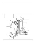
Weider 9025 Uk Manual - Page 8
Arm Assembly
 |
View all Weider 9025 manuals
Add to My Manuals
Save this manual to your list of manuals |
Page 8 highlights
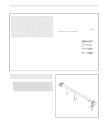
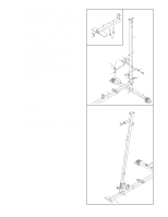
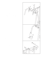
6. Press two 38mm Square Bushings (35) into the Right Pedal (14); Attach a Pedal Cover (36) to the Pedal with two M4 x 16mm Self-tapping Screws (74) and two M4 Washers (75). Lubricate the pedal axles on the Rear Upright (3). Slide the Right Pedal (14) onto the pedal axle. Make sure that the Pedal is on the correct side; the slotted brackets must be on the inside of the Pedal. Hold a 25mm Retainer (98) and 25mm Round Outer Cap (30) against the right pedal axle. The teeth on the Retainer must bend toward the Round Cover Cap (see the inset drawing in step 7). Tap the Retainer and Round Outer Cap onto the pedal axle. Attach the Left Pedal (15) in the same manner. 7. Lubricate the cylinder axles on the Rear Upright (3) with grease. Slide a 16mm Round Bushing (40) and a Resistance Cylinder (37) onto the right cylinder axle. Make sure that the Bushing, Cylinder, and warning decal are oriented as shown. Hold a 16mm Retainer (39) and a 16mm Round Outer Cap (38) against the right cylinder axle. The teeth on the Retainer must bend toward the Outer Cap (see the inset drawing). Tap the Retainer and Outer Cap onto the cylinder axle. Raise the Right Pedal (14) and rest it on the hook at the lower end of the Resistance Cylinder (37). The hook must be in one of the slots under the right Pedal. Repeat this step with the other Resistance Cylinder (37) on the left side of the Rear Upright (3). Tighten the Nylon Locknuts (72, 73) used in steps 2-7. 6 3 35 30 98 74 75 75 Pedal 36 Axle Slotted 14 Brackets 15 7 3 Cylinder Axle 39 38 40 37 Axle 39, 98 30, 38 Warning Decals 37 Hook 14 Arm Assembly 8 8. Press a 50mm x 70mm Inner Cap (103) into the Butterfly Frame (11). Attach the tethers on the two "L"-pins (100) to the Butterfly Frame (11) with an M4 x 16mm Self-tapping Screw (74). Lubricate an M10 x 80mm Bolt (83) with grease. Attach the Butterfly Frame (11) to the Top Frame (6) with the Bolt and an M10 Nylon Locknut (72). Do not overtighten the Locknut; the Butterfly Arm must be able to pivot easily. 8 103 72 6 83 Lubricate 74 11 100
-
 1
1 -
2
-
 3
3 -
 4
4 -
 5
5 -
 6
6 -
 7
7 -
 8
8 -
 9
9 -
 10
10 -
 11
11 -
 12
12 -
 13
13 -
14
-
15
-
16
-
17
-
18
-
19
-
20
-
21
-
22
-
23
-
24
-
25
-
26
-
27
-
28
-
29
-
30
-
31
 |
 |
