Weider 9250 Uk Manual
Weider 9250 Manual
 |
View all Weider 9250 manuals
Add to My Manuals
Save this manual to your list of manuals |
Weider 9250 manual content summary:
- Weider 9250 | Uk Manual - Page 1
& Fitness, Ltd. Unit 4 Revie Road Industrial Estate Revie Road Beeston Leeds, LS118JG UK email: [email protected] CAUTION Read all precautions and instructions in this manual before using this equipment. Save this manual for future reference. USER'S MANUAL Visit our website at www.iconeurope.com - Weider 9250 | Uk Manual - Page 2
YOU BEGIN 4 ASSEMBLY 5 ADJUSTMENTS 21 TROUBLESHOOTING AND MAINTENANCE 24 CABLE DIAGRAMS 25 EXERCISE GUIDELINES 26 ORDERING REPLACEMENT PARTS Back Cover Note: A PART IDENTIFICATION CHART and a PART LIST/EXPLODED DRAWING are attached in the centre of this manual. Remove the PART IDENTIFICATION - Weider 9250 | Uk Manual - Page 3
an exercise that could cause the weight system to tip. ! WARNING • Misuse of this product may result in serious injury. • Read user's manual and follow all warnings and operating instructions prior to use. • Do not allow children on or around machine. • Replace label if damaged, illegible, or - Weider 9250 | Uk Manual - Page 4
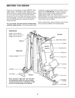
WEIDER® 9250 weight system. The WEIDER® 9250 weight system system, the 9250 will help you to achieve the specific results you want. For your benefit, read this manual carefully before using the weight system. If you have questions after reading this manual, please call our Customer Service - Weider 9250 | Uk Manual - Page 5
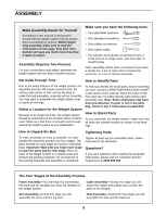
after reading the assembly instructions, please call our Customer Service Department at 0845 089 009. The Four Stages of the Assembly Process Frame Assembly-You will begin by assembling the base and the uprights that form the skeleton of the weight system. Cable Assembly-During this stage - Weider 9250 | Uk Manual - Page 6
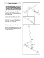
FRAME ASSEMBLY 1. Before beginning assembly, make sure you have read and understood the information in the box on page 5. This introduction will save you more time than it takes to read it. Press a 40mm x 60mm Outer Cap (10) onto the end of the Stabiliser (5). Press two 40mm x 60mm Inner Caps (27) - Weider 9250 | Uk Manual - Page 7
Upright (88) to the Stabiliser 3 (5) with the indicated two M10 x 55mm Carriage Bolts (1) and two M10 Nylon Locknuts (21). Make sure the Support Upright leans toward the center of the Stabiliser. Attach the Carriage Upright (84) to the Stabiliser (5) with the indicated two M10 x 55mm Carriage - Weider 9250 | Uk Manual - Page 8
the Weight Tube rests in the indicated pin groove. Lubricate the indicated holes in the Top Weight (56). Slide the Top Weight onto the Weight Guides (62), with the pin groove on the side shown. 19 4 21 9 9 60 61 Lubricate 56 63 62 72 Lock Holes 25 Pin Groove Pin Pin - Weider 9250 | Uk Manual - Page 9
Frame (55) on top of the Front 8 Upright (42) and between the Weight Guides (62). Attach the Top Frame to the Front Upright with two M10 x 60mm Nylon Locknuts (21). Do not tight- en the Nylon Locknuts yet. Attach the Weight Guides (62) to the indicated tube on the Top Frame (55) with an M10 - Weider 9250 | Uk Manual - Page 10
11. Press a 38mm Square Inner Cap (32) into the 11 end of the Seat Frame (36). Attach the Bumper (87) to the Seat Frame (36) with the M5 x 20mm Self-tapping Screw (80). 32 36 87 80 12. Attach the Seat Frame (36) to the Front Upright 12 (42) with the M10 x 80mm Carriage Bolt (99) and the - Weider 9250 | Uk Manual - Page 11
. Gently tap the Cover Cap onto the axle. Repeat this step with the Left Butterfly Arm (47). Cable Assembly 16 16. For cable identification and routing during steps 16 to 44, refer to the CABLE DIAGRAMS on page 25. Do not overtighten the locknuts securing the pulley; the pulleys must be able to - Weider 9250 | Uk Manual - Page 12
overtighten the Locknut yet. 55 20 11 103 21 9 15 21 20. Wrap the High Cable (11) under a 90mm Pulley 20 (15). Attach the Pulley and a pair of Pulley tabs on the Pulley Covers are on top. Small Tab 21. Attach the High Cable (11) to the bracket on the 21 Front Upright (42) with an M10 - Weider 9250 | Uk Manual - Page 13
90 23 90 3 11 23 21 Small Tabs 58 40 15 40 58 12 55 15 77 23 77 76 9 21 9 25. Wrap the Weight Cable (23) around a 90mm 25 Pulley (15) and route it down through the Top Frame (55). Attach the Pulley inside the Top Frame with an M10 - Weider 9250 | Uk Manual - Page 14
tabs on the Pulley Covers are on top. 27. Route the Weight Cable (23) up through the Top 27 Frame (55), around the 115mm Pulley M10 Washers (9), and two M10 Nylon Locknuts (21). Attach the Left Upright Bracket (94) to the Support Upright (88) in the same way. 29 21 8 21 94 Hole 8 93 21 8 8 - Weider 9250 | Uk Manual - Page 15
100) and an M10 Nylon Locknut (21). 15 4 21 100 69 31. Wrap the Low Cable (69) around a 90mm Pulley 31 (15). Attach the Pulley and a pair of Pulley Covers shown. 42 21 9 15 40 64 Large Tab 40 69 32. Wrap the Low Cable (69) around a 90mm Pulley 32 (15). Attach the Pulley and a pair of - Weider 9250 | Uk Manual - Page 16
40 104 15 69 9 102 Large Tab 21 40 42 34. Wrap the Low Cable (69) around a 90mm Pulley 34 (15). Attach the Pulley and a pair and an M10 Nylon Locknut (21). 42 21 69 9 50 6 9 8 36. Wrap the Low Cable (69) around a 90mm Pulley 36 (15). Attach the Pulley and a pair of Pulley Covers (40 - Weider 9250 | Uk Manual - Page 17
45mm Bolt (100) and an M10 Nylon Locknut (21). 100 39. Wrap the Carriage Cable (83) around a 90mm 39 Pulley (15) and route it through the hole in the Pulley Covers are on the 40 83 side shown. 15 84 40. Wrap the Carriage Cable (83) up around a 90mm Pulley (15). Attach the Pulley and a pair - Weider 9250 | Uk Manual - Page 18
sure the small tabs on the Pulley Covers are on bottom. 42. Wrap the Carriage Cable (83) under a 90mm 42 Pulley (15). Attach the Pulley and a pair of the small tabs on the Pulley Covers are on top. 43. Wrap the Carriage Cable (83) around a 90mm 43 Pulley (15). Attach the Pulley and a pair - Weider 9250 | Uk Manual - Page 19
Seat Assembly 45 45. Attach the Shroud (59) to the bracket on the Top Frame (55) with two M6 Washers (78) and two M6 x 16mm Bolts (18). Attach the Shroud (59) to the bracket on the Base (4) with two M6 Washers (78) and two M6 x 16mm Bolts (18). 18 78 59 55 18 78 18 78 46. Insert the M6 x 50mm - Weider 9250 | Uk Manual - Page 20
the problem. IMPORTANT: If the cables are not properly installed, they may be damaged when heavy weight is used. See the CABLE DIAGRAMS on page 25 for proper cable routing. If there is any slack in the cables, you will need to remove it by tightening the cables; see TROUBLESHOOTING AND MAINTENANCE - Weider 9250 | Uk Manual - Page 21
) into the indicated hole in one of the Weight Guides (62) and secure the Locking Bar with the Lock (86). Remove the Lock (86) and Locking Bar (85) to use the weight system again. 25 26 62 86 85 ATTACHING THE ACCESSORIES TO THE CABLES Attach the Lat Bar (54) to the High - Weider 9250 | Uk Manual - Page 22
(42). Slot 49 99 Pin 36 42 ATTACHING THE LEG LEVER TO THE LOW CABLE To use the Leg Lever (29), the seat frame must be attached to the front of the Leg Lever (29) with another Cable Clip. ATTACHING THE CURL PAD To attach the Curl Pad (24) to the weight system, the seat frame must be attached to the - Weider 9250 | Uk Manual - Page 23
arm. Note: The actual resistance at each station may vary due to differences in individual weight plates as well as friction between the cables, pulleys, and weight guides. Weight Top 1 2 3 4 5 6 7 8 9 10 11 High Pulley (lbs.) 12 21 29 37 45 53 61 69 79 86 96 104 Butterfly Arm (lbs.) 8 15 - Weider 9250 | Uk Manual - Page 24
TROUBLESHOOTING AND MAINTENANCE Make sure all parts are properly tightened each time the weight system is used. Replace any worn parts immediately. The weight system can be cleaned using a damp cloth and mild non-abrasive detergent. Do not use solvents. TIGHTENING THE CABLES Woven cable cable Cable - Weider 9250 | Uk Manual - Page 25
cable diagrams below show the proper routing of the High Cable (11), the Weight Cable (23), the Low Cable (69), and the Carriage Cable (83). Use the diagram to make sure that the cables and the cable traps have been assembled correctly. If the cables have not been correctly routed, the weight system - Weider 9250 | Uk Manual - Page 26
, and moving only the appropriate parts of the body. Exercising in an uncontrolled manner will leave you feeling exhausted. On the exercise guide accompanying this manual you will find photographs showing the correct form for several exercises, and a list of the muscles affected. Refer to the muscle - Weider 9250 | Uk Manual - Page 27
Rest for a short period of time after each set. The ideal resting periods are: • Rest for three minutes after each set for a muscle building workout. • Rest for one minute after each set for a toning work- out. • Rest for 30 seconds after each set for a weight loss workout. Plan to spend the first - Weider 9250 | Uk Manual - Page 28
when ordering replacement parts: • the MODEL NUMBER of the product (WEEVSY59220) • the NAME of the product (WEIDER® 9250 weight system) • the SERIAL NUMBER of the product (see the front cover of this manual) • the KEY NUMBER and DESCRIPTION of the part(s) (see the PART LIST and EXPLODED DRAWING in - Weider 9250 | Uk Manual - Page 29
number of the part from the PART LIST in the centre of this manual. Important: Some parts may have been pre-assembled for shipping purposes. If is divided into four stages: 1) frame assembly, 2) arm assembly, 3) cable assembly, 4) seat assembly. The hardware for each stage is packaged separately. - Weider 9250 | Uk Manual - Page 30
50mm Square Inner Cap (44) 60mm Square Inner Cap (101) 38mm Square Inner Cap (32) 40mm x 60mm Inner Cap (27) 25mm Square Inner Cap (97) 40mm x 60mm Outer Cap (10) 25mm Retainer (68) 25mm Round Cover Cap (65) 19mm Round Inner Cap (34) - Weider 9250 | Uk Manual - Page 31
PART IDENTIFICATION CHART-Model No. WEEVSY59220 R0702A M10 Nylon Locknut (21) M8 x 45mm Bolt (66) M10 x 45mm Bolt (100) M8 Nylon Locknut (3) M10 x 20mm Bolt (98) M5 x 20mm Self-tapping Screw (80) M10 x 47mm Bolt (103) M6 x 50mm Bolt (33) M6 Nylon Locknut (2) M6 x 16mm Screw (18) M10 x 52mm - Weider 9250 | Uk Manual - Page 32
17.5mm Spacer (77) 15mm Spacer (61) 12.5mm Spacer (82) M10 Thick Spacer (104) M10 x 105mm Bolt (106) M10 x 75mm Bolt (76) M10 x 78mm Bolt (14) M10 x 80mm Bolt (8) M10 x 80mm Carriage Bolt (99) M10 x 92mm Bolt (16) M10 x 110mm Bolt (64) M10 x 115mm Bolt (102) M10 x 120mm Bolt (95) M10 x 135mm Bolt - Weider 9250 | Uk Manual - Page 33
REMOVE THIS PART LIST/EXPLODED DRAWING FROM THE MANUAL. SAVE THIS PART LIST/EXPLODED DRAWING FOR FUTURE REFERENCE Note: Specifications are subject to change without notice. See the back cover of the user's manual for information about ordering replacement parts. 81 - Weider 9250 | Uk Manual - Page 34
20mm Self-tapping Screw Swivel Bracket 12.5mm Spacer Carriage Cable Carriage Upright Locking Bar Lock Bumper Support Upright Carriage Large "U"-Bracket Large Pulley Plate Ankle Strap M10 x 105mm Bolt Key User's Manual Exercise Guide Exercise Chart Decal Note: "#" indicates a non-illustrated part. - Weider 9250 | Uk Manual - Page 35
21 15 15 83 101 71 60 21 83 98 81 100 21 89 101 73 21 71 21 100 9 8 8 84 21 21 15 21 21 21 9 40 12 5 27 1 52 92 8 21 40 9 40 15 9 62 8 12 21 3 8 60 15 74 8 9 94 7 9 27 21 77 1577 9 76 8 6 82 9 76 7 50 77 9 82 50 6 62 93 77 9 55 9 6 21 27 21 21 9 77 21
-
 1
1 -
 2
2 -
 3
3 -
 4
4 -
 5
5 -
 6
6 -
 7
7 -
8
-
9
-
10
-
11
-
12
-
13
-
14
-
15
-
16
-
17
-
18
-
19
-
20
-
21
-
22
-
23
-
24
-
25
-
26
-
27
-
28
-
29
-
30
-
31
-
32
-
33
-
34
-
35
 |
 |
USER'S MANUAL
CAUTION
Read all precautions and instruc-
tions in this manual before using
this equipment. Save this manual
for future reference.
Model No.WEEVSY59220
Serial No.
(Write the serial number in the
space above for reference.)
Serial Number Decal (under seat)
www.iconeurope.com
Visit our website at
QUESTIONS?
As a manufacturer, we are
committed to providing com-
plete customer satisfaction. If
you have questions, or if there
are missing or damaged parts,
please call:
Or write:
ICON Health & Fitness, Ltd.
Unit 4
Revie Road Industrial Estate
Revie Road
Beeston
Leeds, LS118JG
UK
email: [email protected]
08457 089 009