Weider 9250 Uk Manual - Page 7
Nylon Locknuts; the Swivel Bracket must
 |
View all Weider 9250 manuals
Add to My Manuals
Save this manual to your list of manuals |
Page 7 highlights
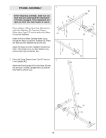
3. Attach the Support Upright (88) to the Stabiliser 3 (5) with the indicated two M10 x 55mm Carriage Bolts (1) and two M10 Nylon Locknuts (21). Make sure the Support Upright leans toward the center of the Stabiliser. Attach the Carriage Upright (84) to the Stabiliser (5) with the indicated two M10 x 55mm Carriage Bolts (1) and two M10 Nylon Locknuts (21). Do not tighten the M10 Nylon Locknuts (21) yet. 88 84 21 21 21 21 1 4. Turn the Carriage Knob (73) counter clockwise 4 and pull it out as far as it will go. Slide the Carriage (89) onto the Carriage Upright (84) and engage the Knob into one of the adjustment holes in the Upright. Fully tighten the Knob. Make sure the Carriage is oriented as shown. Be careful not to scratch the decals on the Upright as you slide the Carriage over them. Attach the Swivel Bracket (81) to the Carriage (89) with an M10 x 155mm Bolt (60) and an M10 Nylon Locknut (21). Do not overtighten the M10 Nylon Locknuts; the Swivel Bracket must be able to pivot easily. Press two 60mm Square Inner Caps (101) into the top of the Carriage Upright (84) and the Support Upright (88). 5 1 101 60 101 89 21 81 84 73 88 Adjustment Hole 7
-
 1
1 -
 2
2 -
 3
3 -
 4
4 -
 5
5 -
 6
6 -
 7
7 -
 8
8 -
 9
9 -
 10
10 -
 11
11 -
 12
12 -
13
-
14
-
15
-
16
-
17
-
18
-
19
-
20
-
21
-
22
-
23
-
24
-
25
-
26
-
27
-
28
-
29
-
30
-
31
-
32
-
33
-
34
-
35
 |
 |
