Weider 9250 Uk Manual - Page 6
Frame Assembly
 |
View all Weider 9250 manuals
Add to My Manuals
Save this manual to your list of manuals |
Page 6 highlights
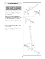
FRAME ASSEMBLY 1. Before beginning assembly, make sure you have read and understood the information in the box on page 5. This introduction will save you more time than it takes to read it. Press a 40mm x 60mm Outer Cap (10) onto the end of the Stabiliser (5). Press two 40mm x 60mm Inner Caps (27) into the ends of the Base (4) and the Stabiliser. Insert six M10 x 55mm Carriage Bolts (1) up through the Base (4) and the Stabiliser (5). Place the Base and the Stabiliser flat on the floor. Attach the Base (4) to the Stabiliser (5) with two M10 x 78mm Bolts (14), two M10 Washers (9), and two M10 Nylon Locknuts (21). 2. Press the 25mm Square Inner Cap (97) into the Front Upright (42). Attach the Front Upright (42) to the Base (4) with the two M10 x 55mm Carriage Bolts (1) and two M10 Nylon Locknuts (21). 1 21 9 9 5 27 1 4 1 2 10 14 1 14 4 27 42 21 4 1 97 21 6
-
 1
1 -
 2
2 -
 3
3 -
 4
4 -
 5
5 -
 6
6 -
 7
7 -
 8
8 -
 9
9 -
 10
10 -
 11
11 -
 12
12 -
13
-
14
-
15
-
16
-
17
-
18
-
19
-
20
-
21
-
22
-
23
-
24
-
25
-
26
-
27
-
28
-
29
-
30
-
31
-
32
-
33
-
34
-
35
 |
 |
