Weider 9400 Instruction Manual - Page 11
Cable Assembly
 |
View all Weider 9400 manuals
Add to My Manuals
Save this manual to your list of manuals |
Page 11 highlights
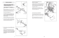
49. Wrap the Swivel Low Cable (72) over a 90mm 49 Pulley (78). Attach the Pulley and a pair of Pulley Covers (68) between the lower set of holes in the "U"-bracket (64) with an M10 x 50mm Bolt (100) and an M10 Nylon Locknut (87). Make sure the small tabs on the Pulley Covers are on the bot- tom. 50. Attach the end of the Swivel Low Cable (72) inside 50 of the Short Base (2) with an M10 x 65mm Bolt (18), two M10 Washers (91), and an M10 Nylon Locknut (87). 100 68 Small Tab 64 72 87 78 68 Small Tab 51. Locate the Squat Cable (73), which is the only 51 remaining cable. Attach the eyelet end of the Cable inside of the Long Base (101) with an M10 x 65mm Bolt (18), two M10 Washers (91), and an M10 Nylon Locknut (87). 52. Wrap the Squat Cable (73) over a 90mm Pulley 52 (78). Attach the Pulley, a pair of Pulley Covers (68), and two 16mm Spacers (98) between the indicated brackets on the Squat Slider (38) with an M10 x 85mm Bolt (96) and an M10 Nylon Locknut (87). Make sure the small tabs on the Pulley Covers are on the bottom. 87 91 72 91 18 2 91 18 73 87 91 101 68 78 98 96 73 68 98 Small 87 Tab 38 18 16. Press a 40mm x 50mm Inner Cap (21) into the Right Butterfly Arm (26). Wet the lower end of the Arm and a Long Pad (54) with soapy water. Slide the Pad onto the Arm. Attach a Press Handle (27) to the Right Butterfly Arm (26) with two M8 x 20mm Button Head Screws (51). Slide the Long Pad (54) down so that the bottom is flush with the lower end of the Arm. Wet the Press Handle with soapy water. Slide a Long Handgrip (28) onto the Press Handle. Press a 25mm Round Inner Cap (29) into the Press Handle. Lubricate an M10 x 50mm Bolt (100) with grease. Attach a Pivot Bracket (70) to the Right Butterfly Arm (26) with the Bolt and an M10 Nylon Locknut (87). Do not overtighten the Locknut; the Pivot Bracket must be able to pivot easily. Repeat this step with the Left Butterfly Arm (25). 17. Lubricate an M10 x 80mm Button Head Bolt (104) and both sides of two Plastic Washers (56) with grease. Attach the Right Butterfly Arm (26) to the Butterfly Frame (47) with the Bolt, the two Plastic Washers, two Butterfly Caps (57), two M10 Washers (91), and an M10 Nylon Locknut (87) as shown. Make sure that the recessed sides of the Plastic Washers are fitted over the welded bushing in the Butterfly Arm. Do not overtighten the Locknut; the Butterfly Arm must be able to pivot easily. Repeat this step with the Left Butterfly Arm (25). 16 26 51 54 Lubricate 100 70 87 21 29 25 28 27 17 104 26 56 91 57 57 91 87 47 25 CABLE ASSEMBLY 18. IMPORTANT: Refer to the Cable Identification Chart on page 26 for help identifying the cables. Do not overtighten the bolts and locknuts attaching the pulleys; the pulleys must be able to turn freely. Locate and open the parts bags labelled "CABLE ASSEMBLY", "PULLEY COVERS", and "PULLEYS." 18 74 78 40 122 30 87 Lubricate the M10 x 165mm Bolt (30) with grease. Attach the Swivel Cage (76) to the Swivel Carriage (46) with the Bolt and an M10 Nylon Locknut (87). Locate the Swivel High Cable (74), which is 3213mm long and has a ball on one end and a threaded bolt on the other end. Wrap the Cable around a 90mm Pulley (78). Attach two Pulleys and the set of Double Covers (40, 122) to the Swivel Cage (76) with two M10 x 50mm Bolts (100) and two M10 Nylon Locknuts (87). 78 100 76 46 87 11
-
 1
1 -
2
-
3
-
4
-
5
-
 6
6 -
 7
7 -
 8
8 -
 9
9 -
 10
10 -
 11
11 -
 12
12 -
 13
13 -
 14
14 -
 15
15 -
 16
16 -
17
-
18
 |
 |
