Weider 9400 Instruction Manual - Page 8
Outer Caps 121 onto the Upright. Slide the Squat
 |
View all Weider 9400 manuals
Add to My Manuals
Save this manual to your list of manuals |
Page 8 highlights
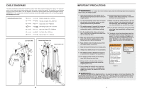
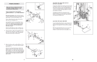
7. Press a 50mm x 75mm Inner Cap (58) into the top of the Squat Upright (4). Press two 25mm Round 7 Outer Caps (121) onto the Upright. Slide the Squat Upright onto the two indicated M10 x 65mm Carriage Bolts (110) in the Long Base (101). Finger tighten an M10 Nylon Locknut (87) onto each Carriage Bolt. Do not tighten the Locknuts yet. Press a 50mm x 75mm Inner Cap (58) into the top of the Swivel Upright (5). Slide the Swivel Upright onto the two indicated M10 x 65mm Carriage Bolts (110) in the Long Base (101). Finger tighten an M10 Nylon Locknut (87) onto each Carriage Bolt. Do not tighten the Locknuts yet. 58 58 5 4 87 110 121 121 101 87 8. Press two Swivel Bushings (66) into the Swivel 8 Carriage (46). Tighten an Adjustment Handle (65) into the Swivel Carriage (46). Orient the Swivel Carriage as shown. Slide the Carriage onto the Swivel Upright (5) and engage the Adjustment Handle into an adjustment hole in the Swivel Upright. 65 66 110 66 46 5 Adjustment Hole 8 61. Turn the Squat Backrest (35) so that the four screw 61 holes are closer to the bottom of the Squat Backrest than the top. Attach the Squat Backrest to the Squat Bracket (37) with four M6 x 16mm Screws (114). 37 114 Fully tighten the Adjustment Knob (115) into the 114 Squat Bracket (37). Turn the knob on the 35 Adjustment Knob counterclockwise several times to loosen it. Next, pull the Adjustment Knob and slide the Squat Bracket (37) down onto the Squat Slider (38). Engage the Adjustment Knob into one of the 115 holes in the Squat Slider, and then turn the Knob clockwise until it is tight. 38 62. Make sure that all parts have been properly tightened. The use of the remaining parts will be explained in ADJUSTMENTS, beginning on the following page. Before using the weight system, pull each cable a few times to make sure that the cables move smoothly over the pulleys. If one of the cables does not move smoothly, find and correct the problem. IMPORTANT: If the cables are not properly installed, they may be damaged when heavy weight is used. See the CABLE DIAGRAMS on page 26 and 27 of this manual for proper cable routing. If there is any slack in the cables, you will need to remove the slack by tightening the cables. See TROUBLESHOOTING on page 25. 21
-
 1
1 -
2
-
 3
3 -
 4
4 -
 5
5 -
 6
6 -
 7
7 -
 8
8 -
 9
9 -
 10
10 -
 11
11 -
 12
12 -
 13
13 -
14
-
15
-
16
-
17
-
18
 |
 |
