Weider 9400 Instruction Manual - Page 4
Before You Begin, Troubleshooting - pro replacement parts
 |
View all Weider 9400 manuals
Add to My Manuals
Save this manual to your list of manuals |
Page 4 highlights
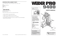
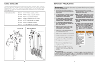
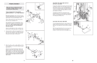
BEFORE YOU BEGIN Thank you for selecting the versatile WEIDER® PRO 9400 weight system. The weight system offers an impressive array of weight stations designed to develop every major muscle group of the body. Whether your goal is to tone your body, build dramatic muscle size and strength, or improve your cardiovascular system, the weight system will help you to achieve the specific results you want. For your benefit, read this manual carefully before using the weight system. If you have questions after reading this manual, please call our Customer Service Department at 08457 089 009. To help us assist you, please note the product model number and serial number before calling. The model number is WEEVSY39530. The serial number can be found on a decal attached to the weight system (see the front cover of this owner's manual). Before reading further, please familiarise yourself with the parts that are labelled in the drawing below. Lat Bar High Pulley Station Swivel Carriage Butterfly Arm/Press Arm WARNING DECAL 1 ASSEMBLED DIMENSIONS: Height: 81 in., 202.5 cm Width: 102 in., 255 cm Length: 52 in., 130 cm WARNING DECAL 2 (one on each side) Adjustment Handle Backrest Low Pulley Station Seat Adjustment Handle Leg Lever Squat Arm Backrest Adjustment Knob WARNING DECAL 2 Weight Stack Squat Knee Rest Handle Curl Bar Ab Strap 4 TROUBLESHOOTING Make sure all parts are properly tightened each time the weight system is used. Replace any worn parts immediately. The weight system can be cleaned using a damp cloth and mild non-abrasive detergent. Do not use solvents. TIGHTENING THE CABLES Woven cable, the type of cable used on the weight system, can stretch slightly when it is first used. If there is slack in the cables before resistance is felt, the cables should be tightened. To tighten the cables, first insert the weight pins into the centres of the weight stacks. Slack can be removed from the cables in several ways: See drawing 1. To tighten the Squat Cable (73) or the Swivel 1 High Cable (not shown), first loosen the M12 Nut (118) on the end of the Cable, away from the 50mm Washer (1). Screw the end of the Cable farther into the Weight Tube (43). Then, retighten the Nut against the Washer. 73 118 1 43 See drawing 2. To further tighten the Squat Cable (73), first remove the M10 Nylon Locknut (87), the M10 x 50mm Bolt 2 (100), the Pulley Covers (68), and the 90mm Pulley (not shown) from the indicated bracket on the Long Base (101). Reattach the Pulley and Pulley Covers between a lower set of holes with the Bolt and Locknut. See drawing 3. To tighten the other five cables, first remove the upper or lower M10 Nylon Locknut (87), M10 x 50mm 3 Bolt (100), 90mm Pulley (not shown), and Pulley Covers (68) from the Pulley Plates (63) or Small Pulley Plates (not shown). Reattach the Pulley and the Pulley Covers between a set of holes closer to the centre of the Pulley Plates. See drawing 4. To remove additional slack, first remove the M10 Nylon Locknut (87), M10 x 50mm Bolt (100), 90mm Pulley (not shown), and Pulley Covers (68) from the "U"bracket (64). Reattach the Pulley and the Pulley Covers between the higher set of holes in the "U"-bracket. Slack can also be removed from the cables by tightening the 4 M8 Nylon Locknut (34) at the end of the Leg Lever Cable (75). To do this you may need to remove the 90mm Pulley (not shown) and Pulley Covers (68) from the "U"-Bracket (64). Do not overtighten the cables. If the cables are overtightened, the top weights will be lifted off the weight stacks. If a cable slips off the pulleys repeatedly, it may have become twisted. Remove the cable and re-install it. If the cables need to be replaced, see ORDERING REPLACEMENT PARTS on the back cover of this manual. 25 73 87 68 101 100 63 100 68 87 75 100 34 64 68 87
-
 1
1 -
 2
2 -
 3
3 -
 4
4 -
 5
5 -
 6
6 -
 7
7 -
 8
8 -
 9
9 -
 10
10 -
11
-
12
-
13
-
14
-
15
-
16
-
17
-
18
 |
 |
