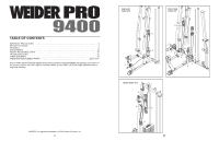
Weider 9400 Instruction Manual - Page 6
Frame Assembly
 |
View all Weider 9400 manuals
Add to My Manuals
Save this manual to your list of manuals |
Page 6 highlights
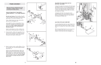
FRAME ASSEMBLY 1 1. Make sure that you understand all of the information on page 5 before you begin assembling the weight system. 2 24 120 14 Locate and open the parts bags labelled "FRAME ASSEMBLY 1" and "FRAME ASSEMBLY 2." See the inset drawing. Attach the Base Cap (24) to the Short Base (2) with two M4 x 20mm Self-tapping Screws (14) and two M4 Washers (120). Press a 50mm Square Inner Cap (105) into the open end of the Long Base (101). Insert eight M10 x 65mm Carriage Bolts (110) up through the Long Base (101) and the Short Base (2) as shown. Note: It may be helpful to place tape over the heads of the Carriage Bolts to hold them in place. Attach the Short Base (2) to the Long Base (101) with two M10 x 70mm Bolts (85), the Long Frame 2. Press two 50mm x 75mm Inner Caps (58) into the Foot Plate (53). Attach the Foot Plate to the Long Base (101) with two M10 x 65mm Carriage Bolts (110) and two M10 Nylon Locknuts (87). 110 87 2 110 87 110 71 85 101 110 105 2 110 58 53 87 58 87 101 3. Attach the tether on the Long Pin w/Tether (112) to 3 the Long Base (101) with an M4 x 20mm Self-tap- ping Screw (14). Attach the four Knee Rest Bumpers (108) to the Squat Knee Rest (41) with four M4 x 20mm Selftapping Screws (14). Attach the Squat Knee Rest to the Long Base (101) with an M10 x 85mm Bolt (96) and an M10 Nylon Locknut (87). Do not overtighten the Locknut; the Squat Knee Rest must be able to pivot. 6 14 101 87 112 96 41 108 14 108 108 14 ADJUSTING THE SQUAT ARM, SEAT, OR BUTTERFLY BACKREST To adjust the height of the Squat Arm (32), first loosen the Adjustment Knob (115) on the Squat Bracket (37). Next, pull the Handle and slide the Squat Bracket up or down to the desired position. Engage the Handle into one of the holes in the Squat Slider (not shown), and retighten the Handle. The height of the Seat (16), the position of the Butterfly Backrest (15), and the Swivel Carriage (not shown) can be adjusted in the same way using the three Adjustment Handles (65). 15 16 65 ADJUSTING THE SQUAT KNEE REST To use the Squat Knee Rest (41), pivot it down to the position shown and insert the Pin w/Tether (112) into the holes in the Squat Knee Rest and the Long Base (101). When the Squat Knee Rest (41) is not in use, pivot it up to a vertical position and then insert the Pin w/Tether (112) into the hole in the Long Base (101). 32 65 37 115 112 101 41 23
-
 1
1 -
 2
2 -
 3
3 -
 4
4 -
 5
5 -
 6
6 -
 7
7 -
 8
8 -
 9
9 -
 10
10 -
 11
11 -
 12
12 -
13
-
14
-
15
-
16
-
17
-
18
 |
 |
