Weider 9400 Instruction Manual - Page 9
water. Slide a Short Pad 20 onto the Squat Arm
 |
View all Weider 9400 manuals
Add to My Manuals
Save this manual to your list of manuals |
Page 9 highlights
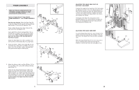
57. Press two 20mm x 40mm Inner Caps (116) and a 57 25mm x 40mm Inner Cap (117) into the Seat Bracket (11). Attach the Seat (16) to the Seat Bracket (11) with two M6 x 16mm Screws (114), an M6 x 35mm Screw (99), and an M6 Washer (97). Loosen the indicated Adjustment Handle (65). Next, pull the Handle and insert the Seat Bracket (11) into the Seat Frame (8). Engage the Handle into one of the holes in the Seat Bracket, and retighten the Handle. 58. Press two 20mm x 40mm Inner Caps (116) and a 58 25mm x 40mm Inner Cap (117) into the Backrest Bracket (13). Attach the Butterfly Backrest (15) to the Backrest Bracket (13) with four M6 x 16mm Screws (114). Loosen the indicated Adjustment Handle (65). Next, pull the Handle and insert the Backrest Bracket (13) into the Butterfly Upright (3). Engage the Handle into one of the holes in the Backrest Bracket and retighten the Handle. 16 116 11 97 116 114 117 99 8 65 116 3 15 114 65 117 114 13 116 59. Wet one end of the Squat Arm (32) with soapy water. Slide a Short Pad (20) onto the Squat Arm as shown. Attach a Squat Handle (33) to the Squat Arm (32) with two M8 x 20mm Button Head Screws (51). Slide an Outer Cap w/Hole (111) onto the Squat Handle and press it onto the end of the Squat Arm. Wet the Squat Handle with soapy water. Slide a 200mm Handgrip (84) onto the Squat Handle. Repeat this step with the other end of the Squat Arm (32). 60. Attach the Squat Arm (32) to the Squat Bracket (37) with two M10 x 65mm Carriage Bolts (110) and two M10 Nylon Locknuts (87). Do not tighten the Locknuts yet. Finish attaching the Squat Arm (32) to the Squat Bracket (37) with two M10 x 70mm Carriage Bolts (106), two M10 Washers (91), and two M10 Nylon Locknuts (87). Tighten all of the M10 Nylon Locknuts (87) used in this step. 59 20 32 51 20 51 33 111 84 60 87 91 87 91 32 110 106 37 20 9. Attach a Roller (39) between the indicated set of 9 holes in the Squat Slider (38) with an M8 x 85mm Bolt (94) and an M8 Nylon Locknut (34). Do not overtighten the Locknut; the Roller must be able to roll easily. Assemble the other three Rollers (39) to the Squat Slider (38) in the same manner. 39 38 39 34 94 39 10. Orient the Squat Slider (38) as shown, and slide it 10 down onto the Squat Upright (4). 38 11. Insert the ends of two Weight Guides (42) without 11 holes into the indicated bracket on the Long Base (101). Slide two Weight Bumpers (49) onto the Weight Guides. Next, slide ten Weights (44) onto the Weight Guides. Make sure that the Weights are turned so the grooved sides of the Weights are facing downward. Press a Weight Tube Bumper (48) into the lower end of a Weight Tube (43). Insert the Weight Tube into the centres of the Weights (44). Make sure that the Weight Tube is turned as shown. Lubricate the two outer holes in a Top Weight (45). Slide the Top Weight onto the Weight Guides (42). Make sure that the Top Weight is turned so the grooved side is facing downward. Apply a number "10" decal to the Top Weight (45) in the location shown. Apply decals with the numbers 20 through 110 to the ten Weights (44). Assemble the other weight stack in the same way. 9 4 42 42 45 Lubricate "10" Decal 43 Groove 48 44 "20" Decal "110" Decal 49 101
-
 1
1 -
2
-
3
-
 4
4 -
 5
5 -
 6
6 -
 7
7 -
 8
8 -
 9
9 -
 10
10 -
 11
11 -
 12
12 -
 13
13 -
 14
14 -
15
-
16
-
17
-
18
 |
 |
