Weider Pro 2000 Uk Manual - Page 10
Cable Assembly - cable diagram
 |
View all Weider Pro 2000 manuals
Add to My Manuals
Save this manual to your list of manuals |
Page 10 highlights
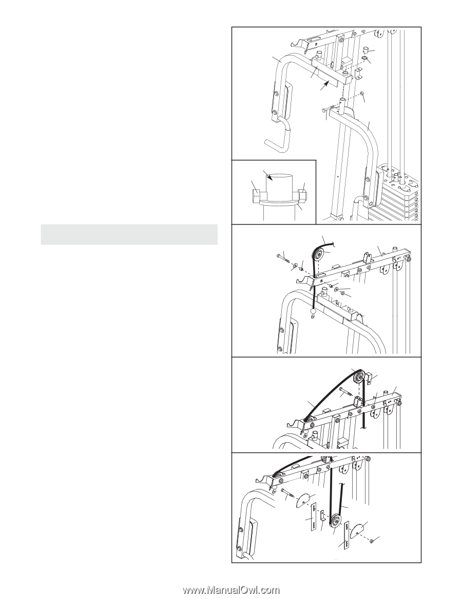
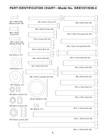
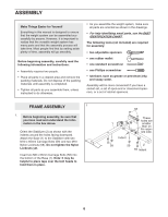
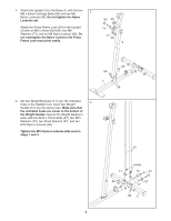
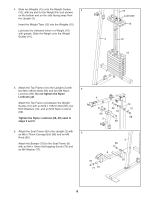
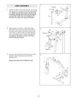
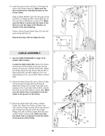
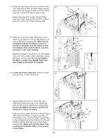
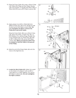
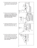
10. Insert the post on the Left Arm (7) through the hole in the Press Frame (5). Make sure the Arm is behind the indicated bracket on the Press Frame. Slide a 25mm Washer (29) over the post on the Left Arm (7). Attach an M6 x 43mm Bolt (61) to the post with an M6 Nylon Locknut (72). Make sure the Nylon Locknut and the head of the Bolt are over the edge of the Washer, as shown in the inset drawing. Press a 25mm Round Outer Cap (27) onto the post on the Left Arm (7). Repeat this step with the Right Arm (6). 10 6 Post 61 5 Bracket 61 72 27 29 72 7 CABLE ASSEMBLY 11 11. See the CABLE DIAGRAM on page 19 for proper cable routing. Locate the High Cable (50). Route the threaded shaft end of the Cable up through the Top Frame (4) and over a 90mm Pulley (34). Attach the Pulley inside the Top Frame with an M10 x 65mm Bolt (55), two M10 Washers (70), two Small Spacers (37), and an M10 Nylon Locknut (68). 12. Route the High Cable (50) over a 90mm Pulley 12 (34) and down through the Top Frame (4). Attach the Pulley and a Cable Trap (36) to the bracket on the Top Frame with an M10 x 52mm Bolt (52) and an M10 Nylon Locknut (68). Make sure the Cable Trap is oriented to hold the Cable in the groove of the Pulley. 29 50 55 4 37 34 70 37 70 68 34 36 4 68 50 52 13. Route the High Cable (50) under a 90mm 13 Pulley (34). Attach the Pulley, a Cable Trap (36), and two Finger Guards (35) to the second set of holes from the top of the two Pulley Plates (44) with an M10 x 52mm Bolt (52) and an M10 Nylon Locknut (68). Make sure that the Cable Trap is oriented to hold the Cable in the groove of the Pulley. 10 52 44 35 50 35 36 34 68 44
-
 1
1 -
2
-
3
-
4
-
 5
5 -
 6
6 -
 7
7 -
 8
8 -
 9
9 -
 10
10 -
 11
11 -
 12
12 -
 13
13 -
 14
14 -
 15
15 -
16
-
17
-
18
-
19
-
20
-
21
-
22
-
23
-
24
 |
 |