Weider Pro 2000 Uk Manual - Page 16
Bleshooting And Maintenance - weight
 |
View all Weider Pro 2000 manuals
Add to My Manuals
Save this manual to your list of manuals |
Page 16 highlights
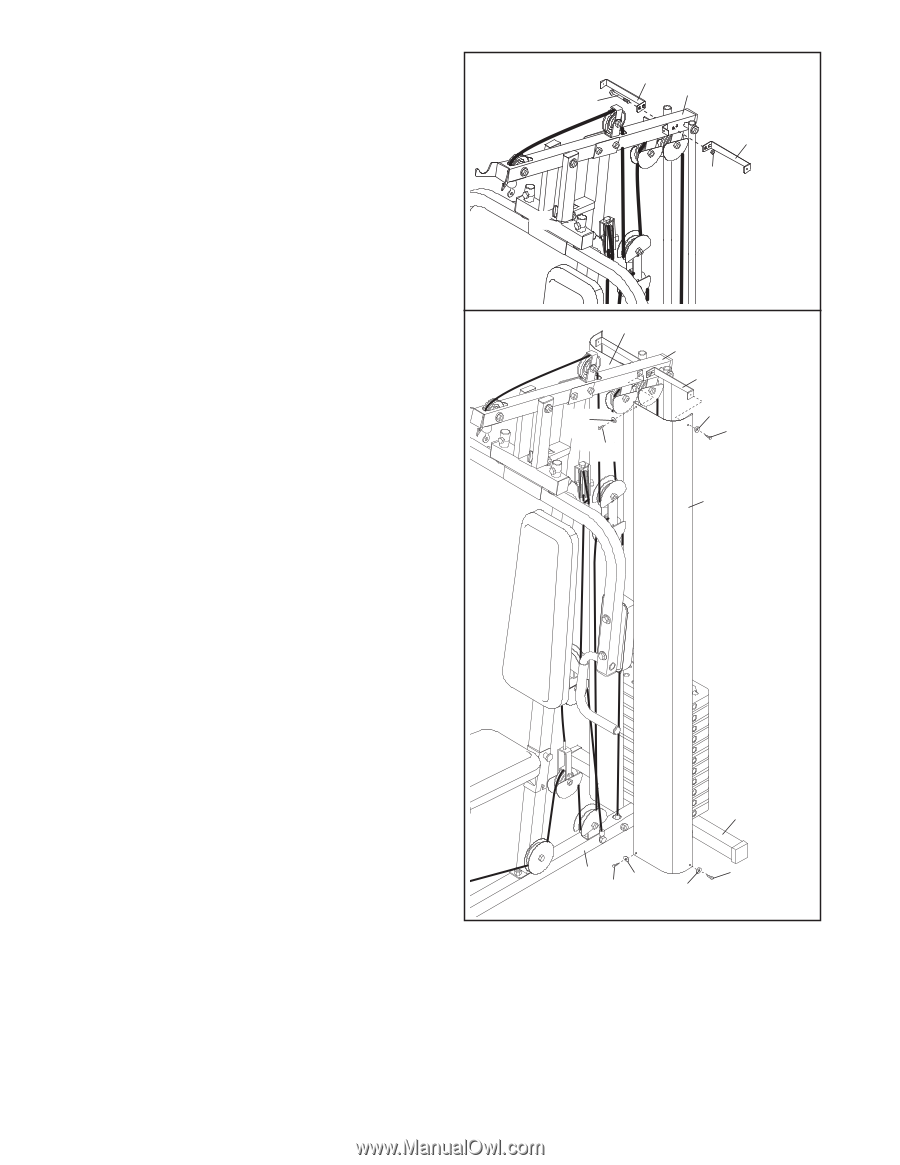
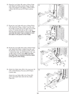
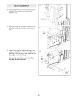
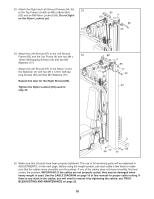
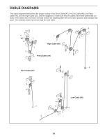
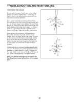
33. Attach the Right and Left Shroud Frames (84, 85) 33 to the Top Frame (4) with an M8 x 68mm Bolt (63) and an M8 Nylon Locknut (69). Do not tight- en the Nylon Locknut yet. 63 18 84 4 85 69 34. Attach the Left Shroud (87) to the Left Shroud 34 Frame (85) and the Top Frame (4) with two M4 x 12mm Self-tapping Screws (56) and two M4 Washers (77). Attach the Left Shroud (87) to the Base (1) and the Stabilizer (2) with two M4 x 12mm Self-tapping Screws (56) and two M4 Washers (77). Repeat this step for the Right Shroud (88). Tighten the Nylon Locknut (69) used in step 33. 88 77 56 4 85 77 56 87 2 1 56 77 77 56 35. Make sure that all parts have been properly tightened. The use of all remaining parts will be explained in ADJUSTMENTS, on the next page. Before using the weight system, pull each cable a few times to make sure that the cables move smoothly over the pulleys. If one of the cables does not move smoothly, find and correct the problem. IMPORTANT: If the cables are not properly routed, they may be damaged when heavy weight is used. See the CABLE DIAGRAM on page 19 of this manual for proper cable routing. If there is any slack in the cables, you will need to remove it by tightening the cables; see TROUBLESHOOTING AND MAINTENANCE on page 20. 16
-
 1
1 -
2
-
3
-
4
-
5
-
6
-
7
-
8
-
9
-
10
-
 11
11 -
 12
12 -
 13
13 -
 14
14 -
 15
15 -
 16
16 -
 17
17 -
 18
18 -
 19
19 -
 20
20 -
 21
21 -
22
-
23
-
24
 |
 |