Weider Pro 2000 Uk Manual - Page 7
Tighten the M10 Nylon Locknuts 68 used - press
 |
View all Weider Pro 2000 manuals
Add to My Manuals
Save this manual to your list of manuals |
Page 7 highlights
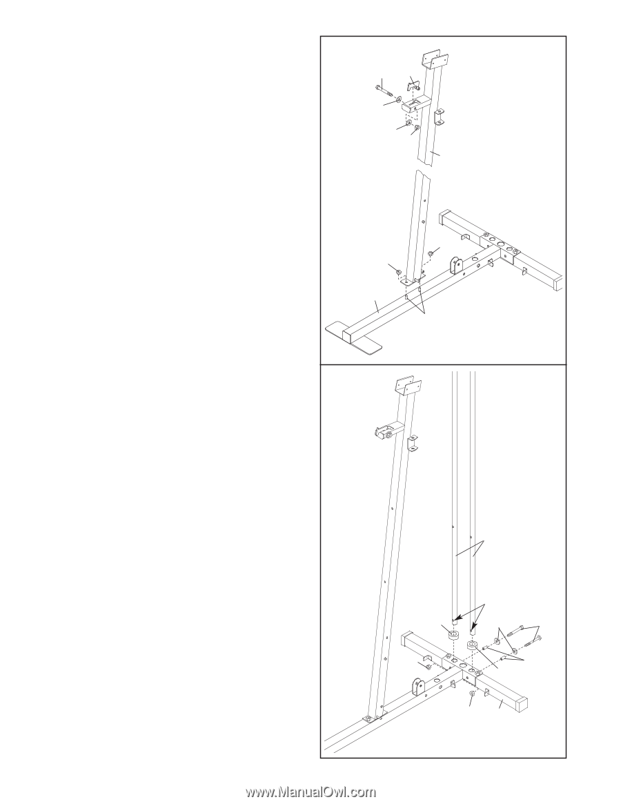
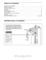
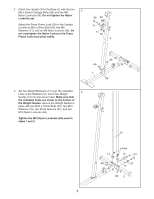
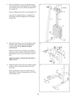
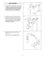
2. Attach the Upright (3) to the Base (1) with the two 2 M8 x 63mm Carriage Bolts (58) and two M8 Nylon Locknuts (69). Do not tighten the Nylon Locknuts yet. Attach the Press Frame Lock (39) to the Upright (3) with an M8 x 63mm Bolt (66), two M8 Washers (71), and an M8 Nylon Locknut (69). Do not overtighten the Nylon Locknut; the Press Frame Lock must pivot easily. 66 39 71 71 69 3 69 69 1 58 3. Set two Weight Bumpers (17) over the indicated 3 holes in the Stabilizer (2). Insert two Weight Guides (10) into the same holes. Make sure that the indicated holes are closer to the bottom of the Weight Guides. Secure the Weight Guides in place with two M10 x 70mm Bolts (57), two M10 Washers (70), two Small Spacers (37), and two M10 Nylon Locknuts (68). Tighten the M10 Nylon Locknuts (68) used in steps 1 and 3. 10 17 68 Holes 70 57 37 17 68 2 7
-
 1
1 -
 2
2 -
 3
3 -
 4
4 -
 5
5 -
 6
6 -
 7
7 -
 8
8 -
 9
9 -
 10
10 -
 11
11 -
 12
12 -
13
-
14
-
15
-
16
-
17
-
18
-
19
-
20
-
21
-
22
-
23
-
24
 |
 |