Weider Pro 2000 Uk Manual - Page 6
Assembly - assembly instructions
 |
View all Weider Pro 2000 manuals
Add to My Manuals
Save this manual to your list of manuals |
Page 6 highlights
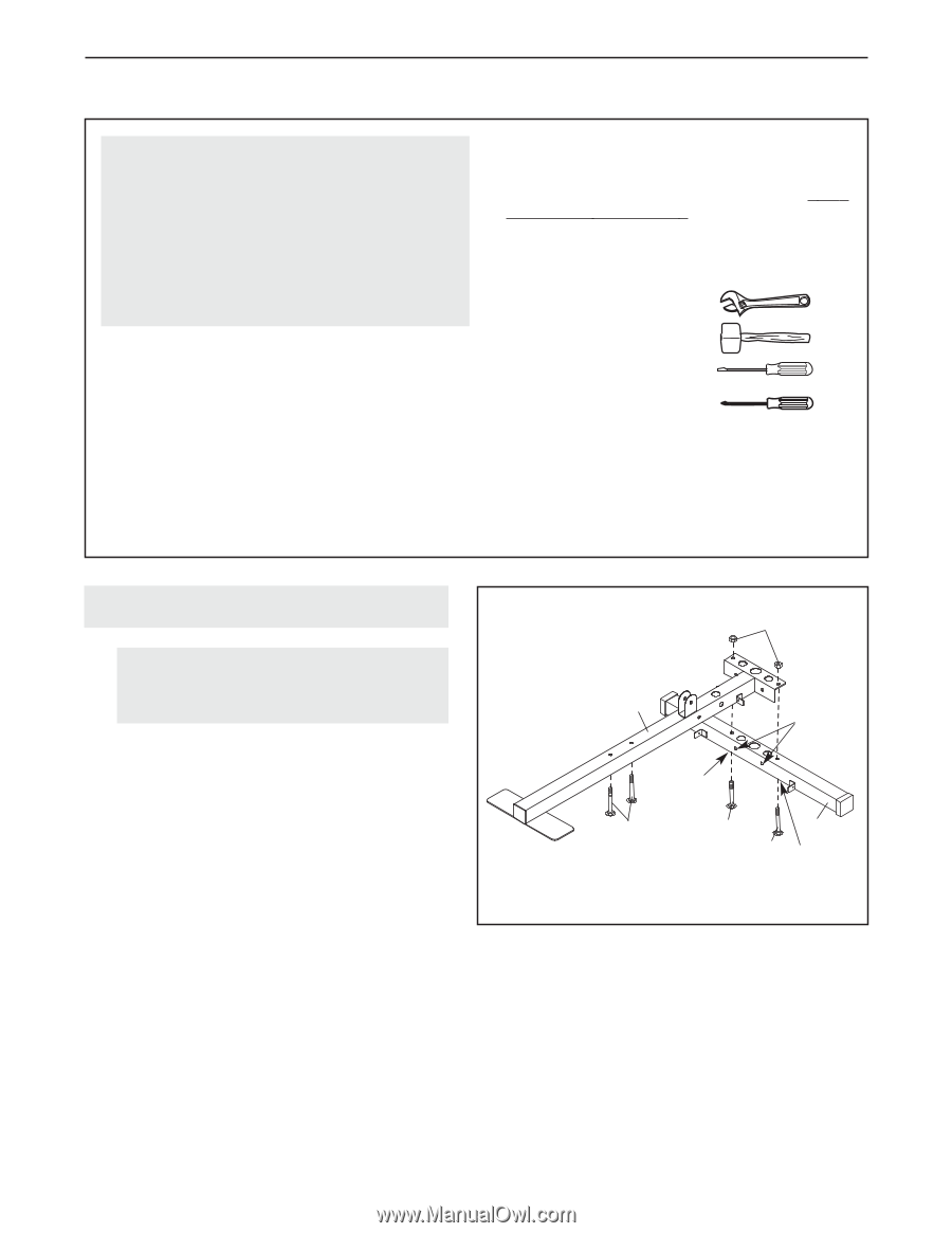
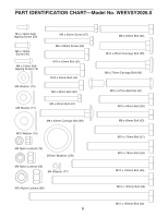
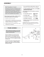
ASSEMBLY Make Things Easier for Yourself Everything in this manual is designed to ensure that the weight system can be assembled successfully by anyone. However, it is important to realize that the versatile weight system has many parts and that the assembly process will take time. Most people find that by setting aside plenty of time, assembly will go smoothly. Before beginning assembly, carefully read the following information and instructions: • Assembly requires two people. • Place all parts in a cleared area and remove the packing materials. Do not dispose of the packing materials until assembly is completed. • Tighten all parts as you assemble them, unless instructed to do otherwise. • As you assemble the weight system, make sure all parts are oriented as shown in the drawings. • For help identifying small parts, use the PART IDENTIFICATION CHART. The following tools (not included) are required for assembly: • two adjustable spanners • one rubber mallet • one standard screwdriver • one Phillips screwdriver • lubricant, such as grease or petroleum jelly, and soapy water. Assembly will be more convenient if you have a socket set, a set of open-end or closed-end spanners, or a set of ratchet spanners. FRAME ASSEMBLY 1 1. Before beginning assembly, be sure that you have read and understand the information in the box above. Orient the Stabilizer (2) as shown with the indents around the holes facing downward. Attach the Base (1) to the Stabilizer with two M10 x 65mm Carriage Bolts (59) and two M10 Nylon Locknuts (68). Do not tighten the Nylon Locknuts yet. Insert two M8 x 63mm Carriage Bolts (58) into the bottom of the Base (1). Note: It may be helpful to place tape over the bolt heads to hold them in place. 68 1 Indent These holes are smaller than on the opposite side. 58 59 2 59 Indent 6
-
 1
1 -
 2
2 -
 3
3 -
 4
4 -
 5
5 -
 6
6 -
 7
7 -
 8
8 -
 9
9 -
 10
10 -
 11
11 -
 12
12 -
13
-
14
-
15
-
16
-
17
-
18
-
19
-
20
-
21
-
22
-
23
-
24
 |
 |