Weider Pro 8000 Uk Manual
Weider Pro 8000 Manual
 |
View all Weider Pro 8000 manuals
Add to My Manuals
Save this manual to your list of manuals |
Weider Pro 8000 manual content summary:
- Weider Pro 8000 | Uk Manual - Page 1
write: ICON Health & Fitness, Ltd. Unit 4 Revie Road Industrial Estate Revie Road Beeston Leeds, LS118JG UK email: [email protected] CAUTION Read all precautions and instructions in this manual before using this equipment. Save this manual for future reference. USERʼS MANUAL - Weider Pro 8000 | Uk Manual - Page 2
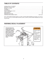
27 CABLE DIAGRAMS 28 MAINTENANCE 30 EXERCISE GUIDELINES 31 ORDERING REPLACEMENT PARTS Back Cover Note: A PART IDENTIFICATION CHART and a PART LIST/EXPLODED DRAWING are attached in the center of this manual. Remove the PART IDENTIFICATION CHART and PART LIST/EXPLODED DRAWING before beginning - Weider Pro 8000 | Uk Manual - Page 3
from moving parts. WARNING: Before beginning this or any exercise program, consult your physician. This is especially important for persons over the age of 35 or persons with pre-existing health problems. Read all instructions before using. Sears assumes no responsibility for personal injury or - Weider Pro 8000 | Uk Manual - Page 4
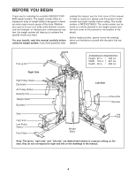
Thank you for selecting the versatile WEIDER® PRO 8000 weight system. The weight system offers of this manual for the location of the decal). Before reading further, please review the drawing below and familiarize yourself with the parts that are labeled. Pull-up Arm ASSEMBLED DIMENSIONS: Height: - Weider Pro 8000 | Uk Manual - Page 5
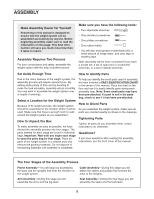
set, a set of open-end or closed-end wrenches, or a set of ratchet wrenches. Set PART IDENTIFICATION CHART in the center of this manual. Place the chart on the instructed to do otherwise. Questions? If you have questions after reading the assembly instructions, see the front cover of this manual - Weider Pro 8000 | Uk Manual - Page 6
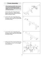
Frame Assembly 1 1. Before beginning assembly, make sure you understand the information in the boxes on page 5. See the PART IDENTIFICATION CHART in the center of this manual for help identifying small parts. Insert four M8 x 75mm Carriage Bolts (84) up through the Right Base (1). Note: It may be - Weider Pro 8000 | Uk Manual - Page 7
5. Attach the Rear Upright (6) to the Rear Base (3) 5 with the two indicated M8 x 75mm Carriage Bolts (84) and two M8 Nylon Locknuts (115). Do not tighten the Locknuts yet. 6 6. Attach the Right Upright (4) to the Right Base (1) 6 with the two indicated M8 x 75mm Carriage Bolts (84) and two - Weider Pro 8000 | Uk Manual - Page 8
7. Attach the Left Upright (5) to the Left Base (2) 7 with the two indicated M8 x 75mm Carriage Bolts (84) and two M8 Nylon Locknuts (115). Do not tighten the Locknuts yet. 5 115 8. Hold the Left Top Frame (8) between the Left Upright (5) and the Rear Upright (6). Attach the Pull-up Arm (19) - Weider Pro 8000 | Uk Manual - Page 9
into the stack of Weights (35). Grease the indicated holes in a Top Weight (34). Slide the Top Weight onto the Weight Guides (24). Repeat this step with the other two Weight Guides (24) and eight Weights (35). 24 24 Grease 34 Pin Holes 36 66 35 35 65 130 116 116 114 1 9 - Weider Pro 8000 | Uk Manual - Page 10
11. Attach a Rear Shroud (25) to the Right Base (1) 11 with two M6 x 12mm Screws (124) and two M6 Washers (132). Make sure that the long holes in the Shroud are near the top. 25 Attach the other Rear Shroud (25) to the Right Base (1) in the same manner. Long Holes 25 12. Attach the Right - Weider Pro 8000 | Uk Manual - Page 11
13. Attach the four Weight Guides (24) to the Right Top Frame (7) with four M10 x 38mm Screws (82) and four M10 Washers (116). Attach a Rear Shroud (25) to the Right Top - Weider Pro 8000 | Uk Manual - Page 12
Arm Assembly 17 17. Grease an M10 x 108mm Bolt (99). Orient the Press Frame (13) so that the welded tube is on the side toward the Left Upright (5). Attach the Press Frame to the Left Base (2) with the Bolt and an M10 Nylon Locknut (114). Do not overtighten the Locknut; the Press Frame must be - Weider Pro 8000 | Uk Manual - Page 13
20. Attach the Leg Bumper (76) to the Right Seat 20 Frame (9) with an M4 x 16mm Self-tapping Screw 114 (113) and an M4 Washer (131). Grease an M10 x 75mm Bolt (104). Attach the Leg Lever (11) to the Right Seat Frame (9) with the Bolt and an M10 Nylon Locknut (114). Make sure the "U"-rod is on - Weider Pro 8000 | Uk Manual - Page 14
Cable Assembly 23. See the CABLE DIAGRAMS on pages 28 and 29 as you assemble the cables and to identify the cables. Locate the Lat Cable (71). Route the Cable up through the Right Top Frame (7) and over a 90mm Pulley (39). Make sure the Cable is between the Pulley and the rod in the Top Frame. - Weider Pro 8000 | Uk Manual - Page 15
28. Route the Lat Cable (71) over a 90mm Pulley 28 (39) and down through the Left Top Frame (8). Attach the Pulley inside the Top Frame with an M10 x 80mm Bolt (111), two M10 Washers (116), two 19mm Spacers (77), and an M10 Nylon Locknut (114). 77 116 114 39 111 77 116 71 8 29. Wrap the - Weider Pro 8000 | Uk Manual - Page 16
33. Wrap the Ab Cable (72) over a "V"-pulley (40). 33 Attach the "V"-pulley, a Cable Trap (49), an M10 Washer (116), and two Full Finger Guards (43) to the Right Upright (4) with an M10 x 61mm Bolt (90) and an M10 Nylon Locknut (114). Make sure the Cable Trap is oriented to hold the Cable in - Weider Pro 8000 | Uk Manual - Page 17
37. Grease the shoulder of an M8 x 22mm Shoulder 37 Bolt (88). Attach the Ab Cable (72) to the bracket on the Right Upright (4) with the Bolt and an M8 Nylon Locknut (115). Make sure the flat edge of the Cable is against the bracket on the Upright. 72 115 88 4 Grease Flat Edge 38. Locate - Weider Pro 8000 | Uk Manual - Page 18
42. Wrap the Leg Lever Cable (70) under a 90mm 42 Pulley (39). Attach the Pulley and two Half Finger Guards (42) to the Right Base (1) with an M10 x 48mm Bolt (101) and an M10 Nylon Locknut (114). 114 42 43. Wrap the Leg Lever Cable (70) over a 90mm 43 Pulley (39). Attach the Pulley, a - Weider Pro 8000 | Uk Manual - Page 19
inside the Top Frame with an M10 x 80mm Bolt (111), two M10 Washers (116), two 19mm Spacers (77), and an M10 Nylon Locknut (114). 48. Set an M12 Washer (129) on top of the Short 48 Weight Tube (123). Thread an M12 Nut (128) all the way onto the Leg Lever - Weider Pro 8000 | Uk Manual - Page 20
), and an M10 Nylon Locknut (114). Make sure the Cable Trap is ori- ented to hold the Cable in the groove of the Pulley. 54. Set an M12 Washer (129) on top of the Long 54 Weight Tube (36). Thread an M12 Nut (128) all the way onto the Right Stack - Weider Pro 8000 | Uk Manual - Page 21
57. Wrap the Press Cable (69) under a "V"-pulley (40). Attach the "V"-pulley, two Half Finger Guards (42), and two M10 Washers (116) to the Leg Press Frame (12) with an M10 x 118mm Bolt (100), an M10 Washer (116), and an M10 Nylon Locknut (114). 58. Wrap the Press Cable (69) under a 90mm Pulley (39 - Weider Pro 8000 | Uk Manual - Page 22
62. Wrap the Press Cable (69) under a 90mm Pulley (39). Attach the Pulley, two M10 Washers (116), 62 and two Half Finger Guards (42) to the Left Base (2) with an M10 x 52mm Bolt (102) and an M10 Nylon Locknut (114). 63. Attach the end of the Leg Press Cable (69) to the 63 "U"-bracket (50) - Weider Pro 8000 | Uk Manual - Page 23
66. Attach the Left Backrest (33) to the Backrest 66 Frame (27) with two M6 x 16mm Screws (85), an M6 x 35mm Screw (139), and an M6 Washer 85 27 5 33 (132). Slide the Backrest Frame (27) into the Left Upright (5). Engage the Knob (121) into the Upright and Backrest Frame, and turn it - Weider Pro 8000 | Uk Manual - Page 24
cables does not move smoothly, find and correct the problem. IMPORTANT: If the cables are not properly installed, they may be damaged when heavy weight is used. See the CABLE DIAGRAMS on pages 28 and 29 of this manual for proper - Weider Pro 8000 | Uk Manual - Page 25
benefit from your exercise program. Also, refer to the accompanying exercise guide to see the correct form for each exercise. Make sure all pulleys, the amount of resistance at each exercise station may vary from the weight setting. Use the WEIGHT RESISTANCE CHART on page 27 to find the approximate - Weider Pro 8000 | Uk Manual - Page 26
). Make sure the Knob is fully tightened. 5 27 33 121 LOCKING THE DIP ASSIST Make sure the Dip Assist (21) is locked when performing an exercise that does not require it. To lock the Dip Assist, engage the Dip Assist Latch (67) over the rod on the Rear Upright (6). 6 21 Rod - Weider Pro 8000 | Uk Manual - Page 27
WEIGHT RESISTANCE CHART The chart below shows the approximate weight resistance at each exercise station. "Top" refers vary due to differences in individual weight plates as well as friction between the cables, pulleys, and weight guides. WEIGHT Top 1 2 3 4 5 6 7 8 9 10 HIGH PULLEY (lbs.) 15 30 44 - Weider Pro 8000 | Uk Manual - Page 28
diagram to make sure that the cables and the cable traps have been assembled correctly. If the cables have not been correctly routed, the weight bench will not function properly and damage may occur. The numbers show the correct route for each cable. Make sure that the cable traps do not - Weider Pro 8000 | Uk Manual - Page 29
7 6 5 4 Lat Cable (71) 6 Length: 16 feet 5 2 4 1 3 8 7 3 10 9 1 Ab Cable (72) Length: 10 feet 3 inches 2 11 6 8 4 Leg Lever Cable (70) 2 Length: 22 feet 3 inches 3 1 7 5 29 - Weider Pro 8000 | Uk Manual - Page 30
be lifted off the weight stack. If a cable tends to slip off the pulleys often, it may have become twisted. Remove the cable and re-install it. If the cables need to be replaced, see ORDERING REPLACEMENT PARTS on the back cover of this - Weider Pro 8000 | Uk Manual - Page 31
guide accompanying this manual you will find photographs showing the correct form for several exercises, and a list of the muscles affected. See the muscle chart on the next page to find the names of the muscles. The repetitions in each set should be performed smoothly and without pausing. The - Weider Pro 8000 | Uk Manual - Page 32
For motivation, keep a record of each workout. The chart on pages 33 and 34 of this manual can be photocopied and used to schedule and record your workouts. List the date, the exercises performed, the resistance used, and the numbers of sets and repetitions completed. Record your weight and key body - Weider Pro 8000 | Uk Manual - Page 33
MONDAY Date: // EXERCISE WEIGHT SETS REPS TUESDAY Date: // WEDNESDAY Date: // AEROBIC EXERCISE EXERCISE WEIGHT SETS REPS THURSDAY Date: // FRIDAY Date: // AEROBIC EXERCISE EXERCISE WEIGHT SETS REPS Make photocopies of this page for scheduling and recording your workouts. 33 - Weider Pro 8000 | Uk Manual - Page 34
MONDAY Date: // EXERCISE WEIGHT SETS REPS TUESDAY Date: // WEDNESDAY Date: // AEROBIC EXERCISE EXERCISE WEIGHT SETS REPS THURSDAY Date: // FRIDAY Date: // AEROBIC EXERCISE EXERCISE WEIGHT SETS REPS Make photocopies of this page for scheduling and recording your workouts. 34 - Weider Pro 8000 | Uk Manual - Page 35
NOTES 35 - Weider Pro 8000 | Uk Manual - Page 36
M10 x 232mm Bolt (108) M6 Locknut (135) M8 Nylon Locknut (115) M10 Nylon Locknut (114) M12 Nut (128) M10 x 77mm Bolt (133) M10 x 75mm Bolt (104) M8 x 72mm Bolt (91) M8 x 70mm Bolt (97) M8 x 69mm Shoulder Bolt (87) M8 Washer (117) M10 Washer (116) M10 x 68mm Bolt (93) M10 x 65mm Bolt (96) M10 x - Weider Pro 8000 | Uk Manual - Page 37
PART IDENTIFICATION CHART See the drawings below to identify small parts used in assembly. The number in parentheses by each drawing is the key number of the part, from the PART LIST in the center of this manual. Note: Some small parts may have been pre-attached. If a part is not in the - Weider Pro 8000 | Uk Manual - Page 38
Arm 18 1 Left Butterfly Arm 19 1 Pull-up Arm 20 1 Dip Arm 21 1 Dip Assist 22 1 Butterfly Frame 23 1 Foot Plate 24 4 Weight Guide 25 2 Rear Shroud 26 4 Shroud Cover 27 1 Backrest Frame 28 1 Right Backrest 29 2 Seat 30 1 Knee Pad 31 2 Pad Tube 32 4 Small - Weider Pro 8000 | Uk Manual - Page 39
Inner Cap M5 x 9mm Screw M5 Washer Left Front Shroud Userʼs Manual Exercise Guide Allen Wrench Grease Packet Note: "#" indicates a non-illustrated part. Specifications are subject to change without notice. See the back cover of the userʼs manual for information about ordering replacement parts. - Weider Pro 8000 | Uk Manual - Page 40
EXPLODED DRAWING A-Model No. WEEVSY3965.0 R1105A 43 116 40 49 59 17 45 90 43 43 40 59 43 92 115 90 115 92 22 88 116 134 114 72 49 57 114 134 115 114 79 55 45 114 55 115 18 43 49 40 43 91 117 90 114 43 95 115 99 114 116 116 39 40 49 72 95 43 116 114 85 58 93 32 - Weider Pro 8000 | Uk Manual - Page 41
EXPLODED DRAWING B-Model No. WEEVSY3965.0 R1105A 54 42 105 134 39 89 37 48 114 56 136 115 105 117 42 114 116 5 102 69 50 134 56 16 16 75 75 116 96 85 140 121 27 120 117 94 117 115 139 132 93 99 140 116 42 114 116 14 97 75 75 33 116 96 97 42 39 42 114 116 14 42 98 - Weider Pro 8000 | Uk Manual - Page 42
EXPLODED DRAWING C-Model No. WEEVSY3965.0 R1105A 30 55 67 116 75 114 43 74 39 43 61 53 74 48 116 108 85 116 116 108 53 61 85 89 117 19 107 114 116 116 61 54 114 116 21 114 61 126 62 42 114 48 64 55 39 108 51 42 126 62 89 117 6 42 51 48 102 39 42 20 71 88 63 - Weider Pro 8000 | Uk Manual - Page 43
EXPLODED DRAWING D-Model No. WEEVSY3965.0 R1105A 26 109 132 109 132 15 111 77 39 77 114 116 94 116 94 117 135 111 77 39 77 114 116 41 116 115 73 125 73 48 39 115 39 115 117 114 111 94 94 117 115 68 117 111116 127 135 54 7 116 111 77 39 141 141 77 39 71 116 114 77 77 77 116 - Weider Pro 8000 | Uk Manual - Page 44
ordering replacement parts: • the MODEL NUMBER of the product (WEEVSY3965.0) • the NAME of the product (WEIDER PRO 8000 weight system) • the SERIAL NUMBER of the product (see the front cover of this manual) • the KEY NUMBER and DESCRIPTION of the part(s) (see the PART LIST and EXPLODED DRAWING in
-
 1
1 -
 2
2 -
 3
3 -
 4
4 -
 5
5 -
 6
6 -
 7
7 -
8
-
9
-
10
-
11
-
12
-
13
-
14
-
15
-
16
-
17
-
18
-
19
-
20
-
21
-
22
-
23
-
24
-
25
-
26
-
27
-
28
-
29
-
30
-
31
-
32
-
33
-
34
-
35
-
36
-
37
-
38
-
39
-
40
-
41
-
42
-
43
-
44
 |
 |
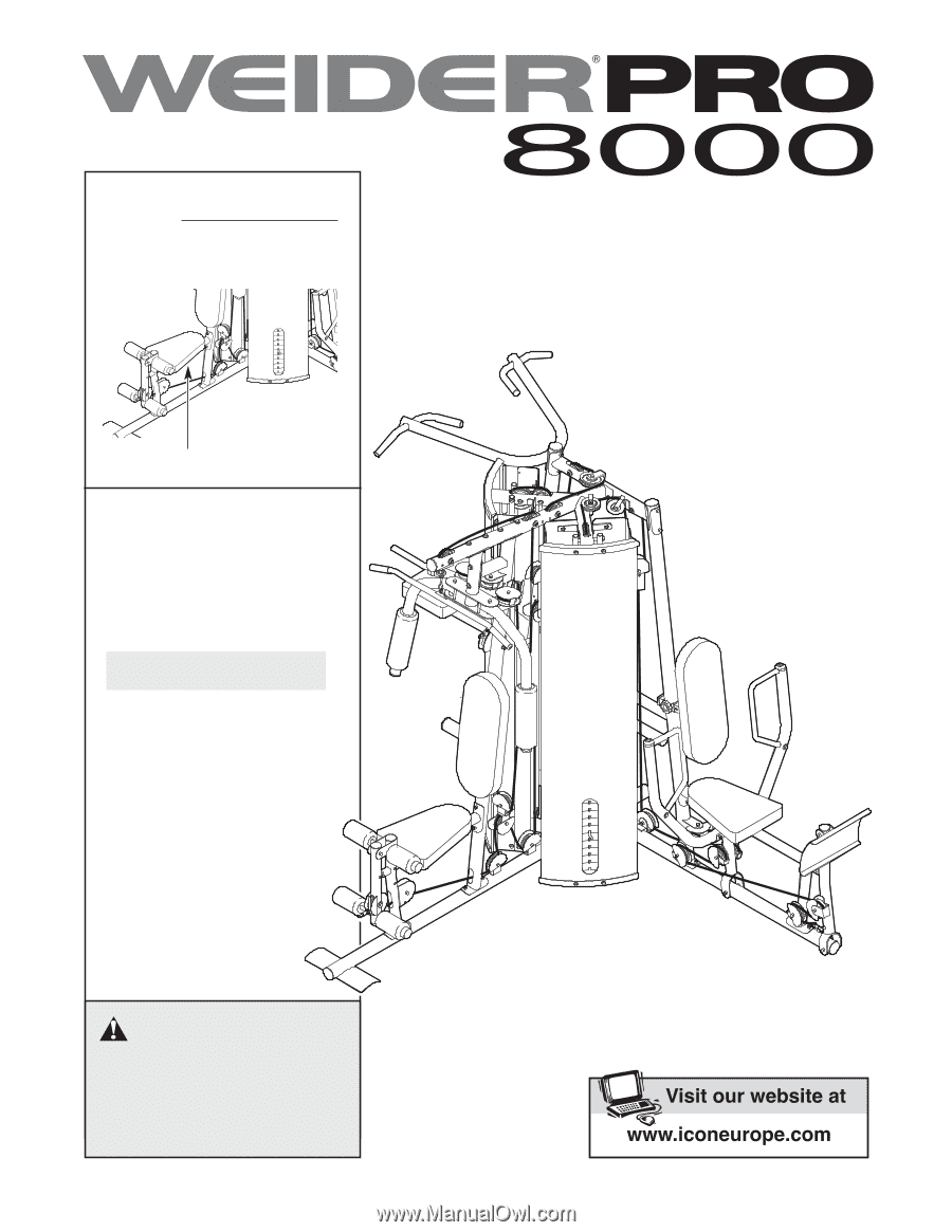
CAUTION
Read all precautions and instruc-
tions in this manual before using
this equipment. Save this manu-
al for future reference.
Model No. WEEVSY3965.0
Serial No.
Write the serial number in the
space above for reference.
Serial Number Decal (under seat)
QUESTIONS?
As a manufacturer, we are com-
mitted to providing complete
customer satisfaction. If you
have questions, or if there are
missing parts, please call:
Or write:
ICON Health & Fitness, Ltd.
Unit 4
Revie Road Industrial Estate
Revie Road
Beeston
Leeds, LS118JG
UK
email: [email protected]
08457 089 009
USERʼS MANUAL