Weider Pro 8000 Uk Manual - Page 12
Arm Assembly
 |
View all Weider Pro 8000 manuals
Add to My Manuals
Save this manual to your list of manuals |
Page 12 highlights
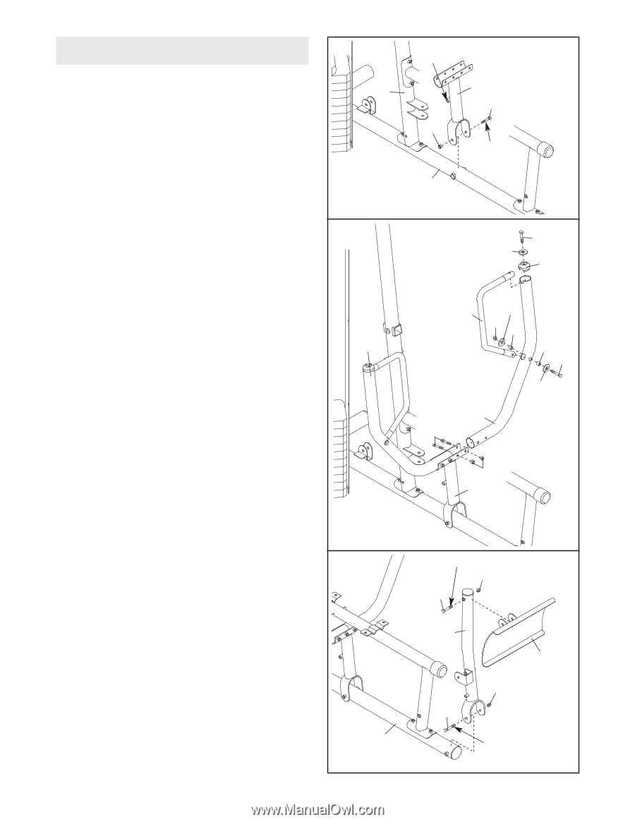
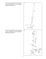
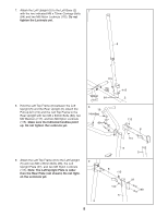
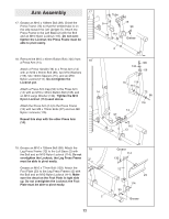
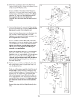
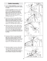
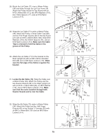
Arm Assembly 17 17. Grease an M10 x 108mm Bolt (99). Orient the Press Frame (13) so that the welded tube is on the side toward the Left Upright (5). Attach the Press Frame to the Left Base (2) with the Bolt and an M10 Nylon Locknut (114). Do not overtighten the Locknut; the Press Frame must be able to pivot easily. Tube 5 13 99 114 Grease 2 18. Remove the M10 x 45mm Button Bolt (105) from a Press Arm (14). Attach a Press Handle (16) to a Press Arm (14) with an M10 x 65mm Bolt (96), two M10 Washers (116), two 12mm Spacers (75), and an M10 Nylon Locknut (114). Do not tighten the Locknut yet. Attach a Press Arm Cap (56) to the Press Arm (14) with an M10 x 45mm Button Bolt (105) and an M10 Large Washer (134). Tighten the M10 Nylon Locknut (114) used above. Attach the Press Arm (14) to the Press Frame (13) with two M8 x 70mm Bolts (97) and two M8 Nylon Locknuts (115). Repeat this step with the other Press Arm (14). 18 14 105 134 56 16 116 114 75 75 96 116 14 97 115 13 19. Grease an M10 x 108mm Bolt (99). Attach the 19 Leg Press Frame (12) to the Left Base (2) with the Bolt and an M10 Nylon Locknut (114). Do not overtighten the Locknut; the Leg Press Frame must be able to pivot easily. Grease an M10 x 77mm Bolt (133). Attach the Foot Plate (23) to the Leg Press Frame (12) with the Bolt and an M10 Nylon Locknut (114). Make sure the decal on the Foot Plate is right side up. Do not overtighten the Locknut; the Foot Plate must be able to pivot easily. 2 12 Grease 114 133 12 23 114 99 Grease
-
 1
1 -
2
-
3
-
4
-
5
-
6
-
 7
7 -
 8
8 -
 9
9 -
 10
10 -
 11
11 -
 12
12 -
 13
13 -
 14
14 -
 15
15 -
 16
16 -
 17
17 -
18
-
19
-
20
-
21
-
22
-
23
-
24
-
25
-
26
-
27
-
28
-
29
-
30
-
31
-
32
-
33
-
34
-
35
-
36
-
37
-
38
-
39
-
40
-
41
-
42
-
43
-
44
 |
 |