Weider Pro 8000 Uk Manual - Page 11
Tighten the M8 Nylon Locknuts 115 used
 |
View all Weider Pro 8000 manuals
Add to My Manuals
Save this manual to your list of manuals |
Page 11 highlights
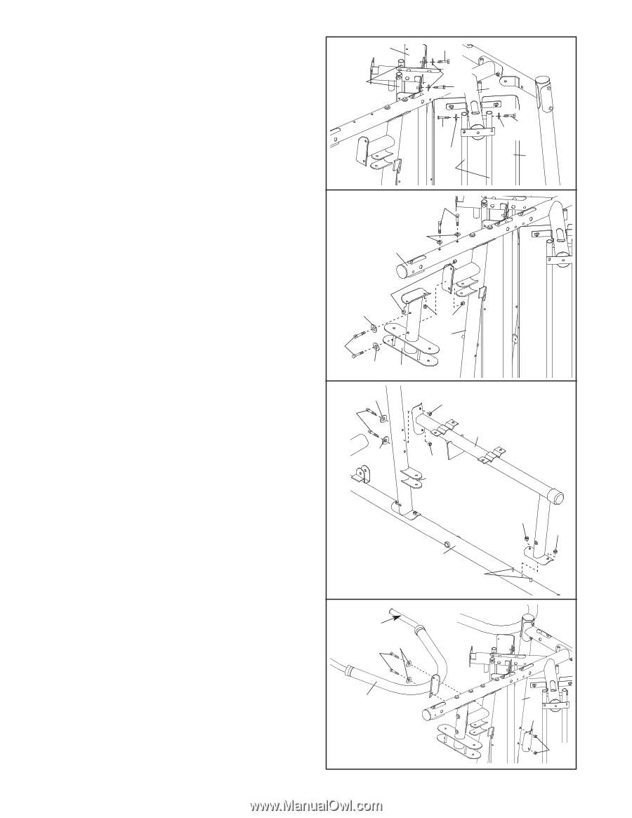
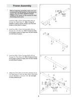
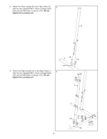
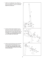
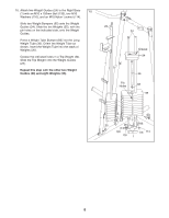
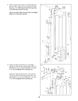
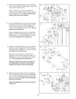
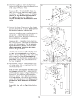
13. Attach the four Weight Guides (24) to the Right Top Frame (7) with four M10 x 38mm Screws (82) and four M10 Washers (116). Attach a Rear Shroud (25) to the Right Top Frame (7) with two M6 x 12mm Screws (124) and two M6 Washers (132). Attach the other Rear Shroud (25) in the same manner. 14. Orient the Butterfly Frame (22) as shown. Attach the Butterfly Frame to the Right Upright (4) with two M8 x 72mm Bolts (91), two M8 Washers (117), and two M8 Nylon Locknuts (115). Do not tighten the Locknuts yet. Attach the Butterfly Frame (22) to the Right Top Frame (7) with two M8 x 80mm Bolts (94), two M8 Washers (117), and two M8 Nylon Locknuts (115). Do not tighten the Locknuts yet. 15. Attach the Left Seat Frame (10) to the Left Base (2) with the two indicated M8 x 75mm Carriage Bolts (84) and two M8 Nylon Locknuts (115). Do not tighten the Locknuts yet. Attach the Left Seat Frame (10) to the Left Upright (5) with two M8 x 80mm Bolts (94), two M8 Washers (117), and two M8 Nylon Locknuts (115). Do not tighten the Locknuts yet. Attach the Right Seat Frame (not shown) to the Right Base (not shown) and the Right Upright (not shown) in the same manner. 16. Attach the Dip Arm (20) to the Rear Upright (6) with two M8 x 83mm Bolts (89), two M8 Washers (117), the Rear Upright Plate (38), and two M8 Nylon Locknuts (115). Make sure the indicated handle is horizontal. Tighten the M8 Nylon Locknuts (115) used in steps 4-15. 13 25 24 124 132 124 7 82 82 116 116 25 24 14 94 117 7 115 117 91 117 22 15 117 94 115 4 115 10 117 115 5 115 115 2 84 16 Handle 89 117 20 6 38 115 11
-
 1
1 -
2
-
3
-
4
-
5
-
 6
6 -
 7
7 -
 8
8 -
 9
9 -
 10
10 -
 11
11 -
 12
12 -
 13
13 -
 14
14 -
 15
15 -
 16
16 -
17
-
18
-
19
-
20
-
21
-
22
-
23
-
24
-
25
-
26
-
27
-
28
-
29
-
30
-
31
-
32
-
33
-
34
-
35
-
36
-
37
-
38
-
39
-
40
-
41
-
42
-
43
-
44
 |
 |