Weider Pro 8000 Uk Manual - Page 15
Locate the Ab Cable 72.
 |
View all Weider Pro 8000 manuals
Add to My Manuals
Save this manual to your list of manuals |
Page 15 highlights
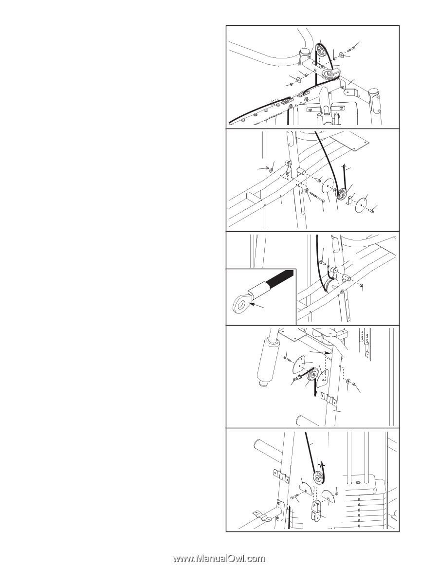
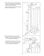
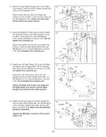
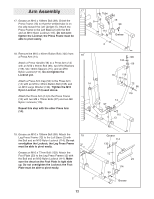
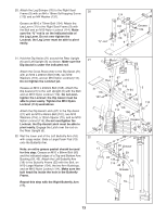
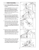
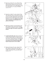
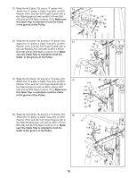
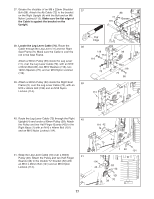
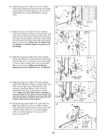
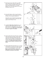
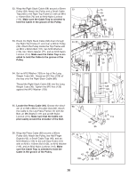
28. Route the Lat Cable (71) over a 90mm Pulley 28 (39) and down through the Left Top Frame (8). Attach the Pulley inside the Top Frame with an M10 x 80mm Bolt (111), two M10 Washers (116), two 19mm Spacers (77), and an M10 Nylon Locknut (114). 77 116 114 39 111 77 116 71 8 29. Wrap the Lat Cable (71) under a 90mm Pulley (39). Attach the Pulley, a Small Cable Trap (48), and two Full Finger Guards (43) to the Dip Assist (21) with an M10 x 232mm Bolt (108), three M10 Washers (116), two 40mm Spacers (74), and an M10 Nylon Locknut (114). Make sure the Cable Trap is oriented to hold the Cable in the groove of the Pulley. 30. Attach the Lat Cable (71) to the bracket on the Rear Upright (6) with an M8 x 22mm Shoulder Bolt (88) and an M8 Nylon Locknut (115). Make sure the flat edge of the Cable is against the bracket. 29 116 114 21 30 71 74 39 48 43 116 43 74 108 116 88 71 6 31. Locate the Ab Cable (72). Wrap the Cable over 31 a 90mm Pulley (39). Attach the Pulley and the two Quarter Guards (95) to the Right Upright (4) with an M10 x 108mm Bolt (99), an M10 Washer (116), and an M10 Nylon Locknut (114). Make sure that the rod is inserted through both Quarter Guards and is over the Cable. 32. Wrap the Ab Cable (72) under a 90mm Pulley (39). Attach the Pulley and two Half Finger 32 Guards (42) to the Double "U"-bracket (52) with an M10 x 48mm Bolt (101) and an M10 Nylon Locknut (114). 115 Flat Edge 99 Rod 95 72 39 116 114 4 72 39 42 114 101 42 52 15
-
 1
1 -
2
-
3
-
4
-
5
-
6
-
7
-
8
-
9
-
 10
10 -
 11
11 -
 12
12 -
 13
13 -
 14
14 -
 15
15 -
 16
16 -
 17
17 -
 18
18 -
 19
19 -
 20
20 -
21
-
22
-
23
-
24
-
25
-
26
-
27
-
28
-
29
-
30
-
31
-
32
-
33
-
34
-
35
-
36
-
37
-
38
-
39
-
40
-
41
-
42
-
43
-
44
 |
 |