Weider Pro 8000 Uk Manual - Page 14
Cable Assembly
 |
View all Weider Pro 8000 manuals
Add to My Manuals
Save this manual to your list of manuals |
Page 14 highlights
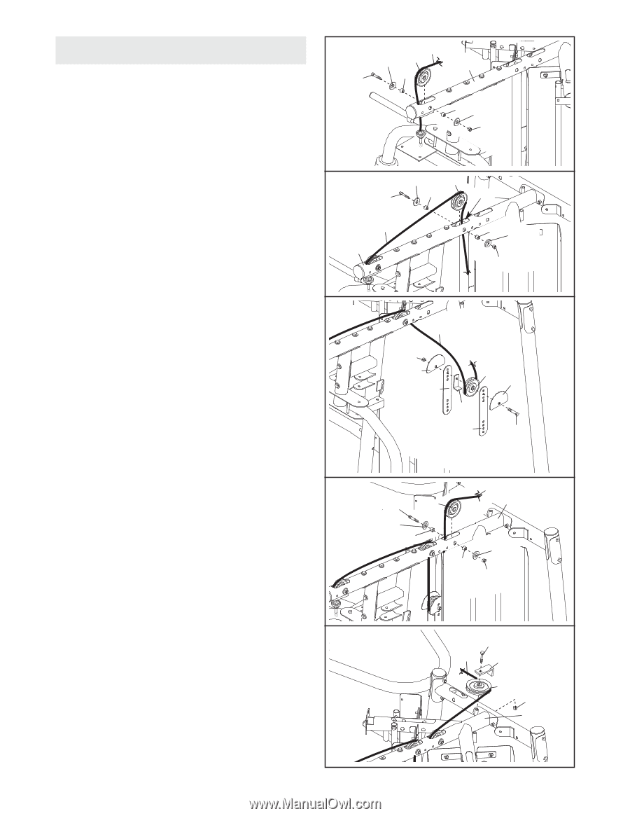
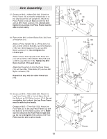
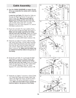
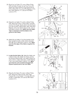
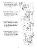
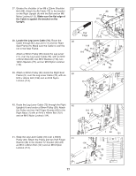
Cable Assembly 23. See the CABLE DIAGRAMS on pages 28 and 29 as you assemble the cables and to identify the cables. Locate the Lat Cable (71). Route the Cable up through the Right Top Frame (7) and over a 90mm Pulley (39). Make sure the Cable is between the Pulley and the rod in the Top Frame. Attach the Pulley inside the Top Frame with an M10 x 80mm Bolt (111), two M10 Washers (116), two 19mm Spacers (77), and an M10 Nylon Locknut (114). 24. Route the Lat Cable (71) over a 90mm Pulley (39) and down through the Right Top Frame (7). Make sure the Cable is between the Pulley and the rod in the Top Frame. Attach the Pulley inside the Top Frame with an M10 x 80mm Bolt (111), two M10 Washers (116), two 19mm Spacers (77), and an M10 Nylon Locknut (114). 25. Wrap the Lat Cable (71) under a 90mm Pulley (39). Attach the Pulley, a Small Cable Trap (48), and two Half Finger Guards (42) at the second hole from the top of the two Pulley Plates (51) with an M10 x 52mm Bolt (102) and an M10 Nylon Locknut (114). Make sure the Cable Trap is oriented to hold the Cable in the groove of the Pulley. 23 71 116 39 77 7 111 77 116 114 24 116 39 111 77 Rod 71 7 77 116 114 25 71 114 42 51 39 42 48 51 102 26. Route the Lat Cable (71) up through the Right Top Frame (7) and over a 90mm Pulley (39). 26 Make sure the Cable is between the Pulley and the rod in the Top Frame. Attach the Pulley inside the Top Frame with an M10 x 80mm Bolt (111), two M10 Washers (116), two 19mm Spacers (77), and an M10 Nylon Locknut (114). 111 39 116 77 71 7 116 77 114 27. Wrap the Lat Cable (71) around a 115mm Pulley 27 (41). Attach the Pulley and a Large Cable Trap (125) to the Right Top Frame (7) with an M10 x 110mm Bolt (73) and an M10 Nylon Locknut (114). Make sure the Cable Trap is oriented to hold the Cable in the groove of the Pulley. 73 71 125 41 114 7 14
-
 1
1 -
2
-
3
-
4
-
5
-
6
-
7
-
8
-
 9
9 -
 10
10 -
 11
11 -
 12
12 -
 13
13 -
 14
14 -
 15
15 -
 16
16 -
 17
17 -
 18
18 -
 19
19 -
20
-
21
-
22
-
23
-
24
-
25
-
26
-
27
-
28
-
29
-
30
-
31
-
32
-
33
-
34
-
35
-
36
-
37
-
38
-
39
-
40
-
41
-
42
-
43
-
44
 |
 |