Weider Pro 8000 Uk Manual - Page 23
Attach the Leg Pin 83 to the Right Seat Frame
 |
View all Weider Pro 8000 manuals
Add to My Manuals
Save this manual to your list of manuals |
Page 23 highlights
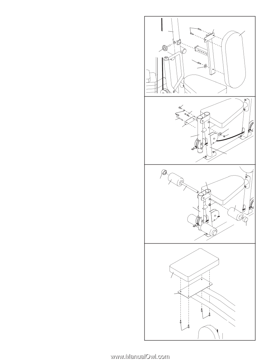
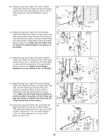
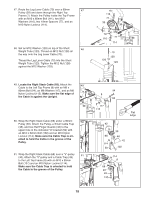
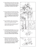
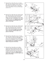
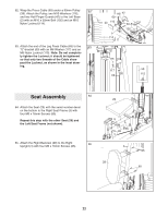
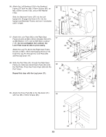
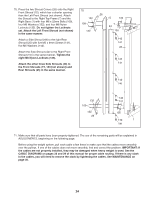
66. Attach the Left Backrest (33) to the Backrest 66 Frame (27) with two M6 x 16mm Screws (85), an M6 x 35mm Screw (139), and an M6 Washer 85 27 5 33 (132). Slide the Backrest Frame (27) into the Left Upright (5). Engage the Knob (121) into the Upright and Backrest Frame, and turn it clockwise 121 until it is tight. 139 132 67. Attach the Lock Plate (80) to the Right Seat 67 Frame (9) with an M8 x 69mm Shoulder Bolt (87), an M8 Washer (117), and an M8 Nylon Locknut (115). Do not overtighten the Locknut; the Lock Plate must be able to pivot easily. Attach the Leg Pin (83) to the Right Seat Frame (9) with an M4 x 16mm Self-tapping Screw (113). Insert the Leg Pin through the Lock Plate (80) and the Leg Lever (11). 113 87 83 80 11 68. Slide the Pad Tube (31) through the Right Seat Frame (9). Slide two Small Foam Pads (32) onto the Pad Tube. Press two Foam Caps (58) into the Pad Tubes. Repeat this step with the Leg Lever (11). 68 58 9 32 31 11 69. Attach the Knee Pad (30) to the Dip Assist (21) 69 with four M6 x 16mm Screws (85). 117 115 9 32 58 30 21 85 85 23
-
 1
1 -
2
-
3
-
4
-
5
-
6
-
7
-
8
-
9
-
10
-
11
-
12
-
13
-
14
-
15
-
16
-
17
-
 18
18 -
 19
19 -
 20
20 -
 21
21 -
 22
22 -
 23
23 -
 24
24 -
 25
25 -
 26
26 -
 27
27 -
 28
28 -
29
-
30
-
31
-
32
-
33
-
34
-
35
-
36
-
37
-
38
-
39
-
40
-
41
-
42
-
43
-
44
 |
 |