Weider Pro 8000 Uk Manual - Page 13
Dip Assist 21 to the Left Upright 5 with the Bolt
 |
View all Weider Pro 8000 manuals
Add to My Manuals
Save this manual to your list of manuals |
Page 13 highlights
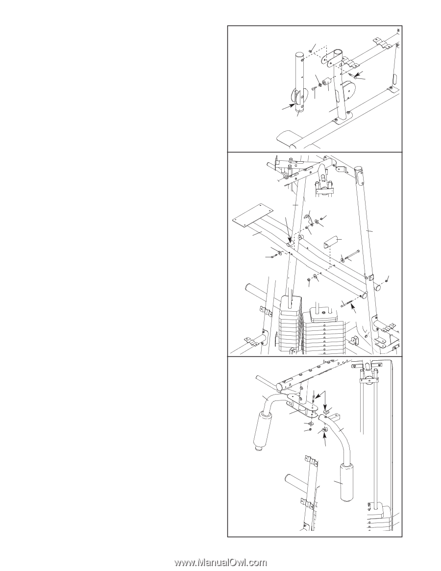
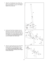
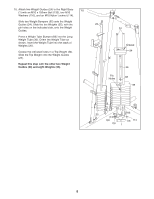
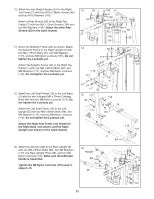
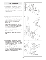
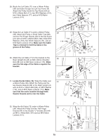
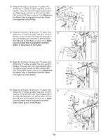
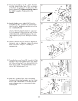
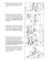
20. Attach the Leg Bumper (76) to the Right Seat 20 Frame (9) with an M4 x 16mm Self-tapping Screw 114 (113) and an M4 Washer (131). Grease an M10 x 75mm Bolt (104). Attach the Leg Lever (11) to the Right Seat Frame (9) with the Bolt and an M10 Nylon Locknut (114). Make sure the "U"-rod is on the indicated side of the Leg Lever. Do not over tighten the Locknut; the Leg Lever must be able to pivot easily. 131 76 113 "U"-rod 9 11 Grease 104 21. Hold the Dip Assist (21) around the Rear Upright (6) and Left Upright (5) as shown. Make sure the Dip Assist is under the indicated rod. Attach the Cross Brace (64) to the Dip Assist (21) with an M10 x 232mm Bolt (108), two M10 Washers (116), and an M10 Nylon Locknut (114). Do not tighten the Locknut yet. Grease an M10 x 232mm Bolt (108). Attach the Dip Assist (21) to the Left Upright (5) with the Bolt and an M10 Nylon Locknut (114). Do not overtighten the Locknut; the Dip Assist must be able to pivot easily. Tighten the M10 Nylon Locknut (114) used above. Attach the Dip Assist Latch (67) to the Dip Assist (21) with an M10 x 85mm Bolt (107), two M10 Washers (116), a 12mm Spacer (75), and an M10 Nylon Locknut (114). Do not overtighten the Locknut; the Dip Assist Latch must be able to pivot easily. Engage the Latch over the rod on the Rear Upright (6). 22. Wet the lower end of the Left Butterfly Arm (18) with soapy water. Slide a Large Foam Pad (79) onto the Butterfly Arm. Note: an entire grease packet should be used for this step. Grease an M10 x 86mm Bolt (92) and the indicated edges of a Top and Bottom Arm Bushing (59, 45). Attach the Left Butterfly Arm (18) to the Butterfly Frame (22) with the Bolt, an M10 Large Washer (134), the two Arm Bushings, and an M10 Nylon Locknut (114). Make sure the bolt head fits inside the hole in the Butterfly Frame. Repeat this step with the Right Butterfly Arm (17). 21 6 Rod 21 116 107 67 114 116 75 64 116 108 116 114 108 5 114 Grease 22 17 92 Grease 59 22 134 18 114 45 Grease 79 13
-
 1
1 -
2
-
3
-
4
-
5
-
6
-
7
-
 8
8 -
 9
9 -
 10
10 -
 11
11 -
 12
12 -
 13
13 -
 14
14 -
 15
15 -
 16
16 -
 17
17 -
 18
18 -
19
-
20
-
21
-
22
-
23
-
24
-
25
-
26
-
27
-
28
-
29
-
30
-
31
-
32
-
33
-
34
-
35
-
36
-
37
-
38
-
39
-
40
-
41
-
42
-
43
-
44
 |
 |