Yamaha F01 Owner's Manual - Page 61
Keyboard Stand Assembly
 |
View all Yamaha F01 manuals
Add to My Manuals
Save this manual to your list of manuals |
Page 61 highlights
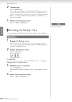
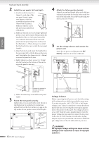
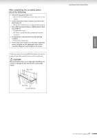
ENGLISH Keyboard Stand Assembly Keyboard Stand Assembly The illustrations here are taken from the F11. CAUTION • Be careful not to confuse parts, and be sure to install all parts in the correct direction. Please assemble in accordance with the sequence given below. • Assembly should be carried out by at least two persons. • Be sure to use the correct screw size, as indicated below. Use of incorrect screws can cause damage. • Be sure to tighten up all screws upon completing assembly of each unit. • To disassemble, reverse the assembly sequence given below. Have a Phillips-head (+) screwdriver ready. Preparing the rear panels When the package is shipped from the factory, the rear panels are secured to the wooden fixing pads with screws. Before you can start assembling the rear panels, you must first remove them from the fixing pads. Removing the panels: Stack two packing pads (included in the packing box with the rear panels) under the rear panels, then remove the screws as shown in the illustrations. CAUTION • Do not use screws fixing rear panels to assem- ble the instrument. Rear panel (center) Fixing pad Remove the following parts from the package. Assembly Parts 6 × 45 mm long screws × 4 1 Rear panels (left, right) Stack two packing pads. 6 × 14 mm short screws × 12 2 Rear panel (left) Rear panel (center) Rear panel (right) Main unit 1 Insert the rear panel (center). Position the rear panel (center) so that the holes face away from the front (keyboard side). Then insert the projections on the panel into the holes on top of the unit, as shown in the illustration. AC power cord keyboard stand stabilizers: 2 pieces Included in the packing pads. CAUTION • When the rear panel (center) is inserted in the main unit, do not apply pressure to the rear panel (center) from the front or rear. Doing so may damage the projections of the rear panel (center), allowing it to fall or be damaged. F11/F01 Owner's Manual 61
-
 1
1 -
2
-
3
-
4
-
5
-
6
-
7
-
8
-
9
-
10
-
11
-
12
-
13
-
14
-
15
-
16
-
17
-
18
-
19
-
20
-
21
-
22
-
23
-
24
-
25
-
26
-
27
-
28
-
29
-
30
-
31
-
32
-
33
-
34
-
35
-
36
-
37
-
38
-
39
-
40
-
41
-
42
-
43
-
44
-
45
-
46
-
47
-
48
-
49
-
50
-
51
-
52
-
53
-
54
-
55
-
 56
56 -
 57
57 -
 58
58 -
 59
59 -
 60
60 -
 61
61 -
 62
62 -
 63
63 -
 64
64 -
 65
65 -
 66
66 -
67
-
68
-
69
-
70
-
71
-
72
-
73
-
74
-
75
-
76
-
77
-
78
 |
 |