Yamaha HTR 5790 MCXSP10 Manual
Yamaha HTR 5790 - Digital Home Theater Receiver Manual
 |
UPC - 027108919744
View all Yamaha HTR 5790 manuals
Add to My Manuals
Save this manual to your list of manuals |
Yamaha HTR 5790 manual content summary:
- Yamaha HTR 5790 | MCXSP10 Manual - Page 1
U HTR-5790 AV Receiver OWNER'S MANUAL - Yamaha HTR 5790 | MCXSP10 Manual - Page 2
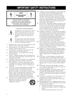
INSTRUCTIONS CAUTION RISK OF ELECTRIC SHOCK DO NOT OPEN CAUTION: TO REDUCE THE RISK OF ELECTRIC SHOCK, DO NOT REMOVE COVER (OR BACK). NO USER-SERVICEABLE PARTS INSIDE. REFER SERVICING TO QUALIFIED SERVICE damage to the product. Use only with a cart, . 13 Power-Cord Protection - Power-supply cords - Yamaha HTR 5790 | MCXSP10 Manual - Page 3
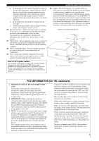
will not result in harmful interference with other electronic devices. This equipment generates/uses radio frequencies and, if not installed and used according to the instructions found in the users manual, may cause interference harmful to the operation of other electronic devices. Compliance with - Yamaha HTR 5790 | MCXSP10 Manual - Page 4
qualified YAMAHA service personnel when any service is needed. The cabinet should never be opened for any reasons. 15 When not planning to use this unit for long periods of time (i.e. vacation), disconnect the AC power plug from the wall outlet. 16 Be sure to read the "TROUBLESHOOTING" section - Yamaha HTR 5790 | MCXSP10 Manual - Page 5
speaker levels 45 Using the test tone 46 SET MENU 47 Using SET MENU 48 Manual setup: SOUND 49 Manual setup: INPUT 54 Manual setup: OPTION 56 REMOTE CONTROL FEATURES 59 Control area 59 Setting manufacturer codes 60 Programming codes from other remote controls ..... 61 Changing source - Yamaha HTR 5790 | MCXSP10 Manual - Page 6
S Video → component video) capability for monitor out ◆ Optical and coaxial digital audio signal jacks ◆ Sleep timer ◆ Night listening mode ◆ Remote control with preset manufacturer codes ◆ Zone 2/Zone 3 custom installation facility (U.S.A., Canada and Australia models only) • y indicates a tip for - Yamaha HTR 5790 | MCXSP10 Manual - Page 7
DISC SKIP POWER AV AMP AUDIO + VOL - LEVEL TITLE TV INPUT + TV VOL SET MENU MENU A/B/C/D/E MUTE CH - PRESET TEST RETURN STEREO 1 TV MUTE SELECT TV VOL - HALL 2 CH + PRESET ON SCREEN DISPLAY STRAIGHT EFFECT JAZZ 3 ROCK 4 ENTERTAIN 5 MUSIC 6 TV THTR 7 MOVIE 8 THX 9 /DTS 0 NIGHT - Yamaha HTR 5790 | MCXSP10 Manual - Page 8
sets it to the standby mode. When you turn on this unit, you will hear a click and there will be a 4 to 5-second delay before this unit can reproduce sound. Note In standby mode, this unit consumes a small amount of power in order to receive infrared-signals from the remote control. 2 Remote control - Yamaha HTR 5790 | MCXSP10 Manual - Page 9
Use to select sound field programs or adjust bass/treble balance (in conjunction with TONE CONTROL). F TONE CONTROL Use to adjust the bass/treble balance for the front left/right and center channels (see page 31). G INPUT MODE Sets the priority (AUTO, DTS, ANALOG) for the type of signals received - Yamaha HTR 5790 | MCXSP10 Manual - Page 10
, or setting manufacturer codes (see page 63). C LEARN Used for setting up the manufacturer code or for programming functions from other remote controls (see pages 60 and 61). D SLEEP Sets the sleep timer. E INPUT MODE Sets the priority (AUTO, DTS, ANALOG) for the type of signals received when one - Yamaha HTR 5790 | MCXSP10 Manual - Page 11
REC DISC SKIP SELECT POWER AV AMP AUDIO VOL LEVEL TITLE TV INPUT TV VOL SET MENU MENU A/B/C/D/E MUTE CH PRESET TEST RETURN STEREO 1 TV MUTE SELECT TV VOL HALL 2 CH PRESET ON SCREEN STRAIGHT DISPLAY EFFECT JAZZ 3 ROCK 4 ENTERTAIN MUSIC 5 6 TV THTR 7 MOVIE 8 THX /DTS NIGHT EX/ES - Yamaha HTR 5790 | MCXSP10 Manual - Page 12
indicator Lights up when a THX program is selected. A PCM indicator Lights up when this unit is reproducing PCM (pulse code modulation) digital audio signals. B Headphones indicator Lights up when headphones are connected. C SP A B indicators Light up according to the set of front speakers selected - Yamaha HTR 5790 | MCXSP10 Manual - Page 13
Indicate the connection of presence and/or surround back speakers when using the SPEAKERS setting (page 29) or SP LEVEL setting (page 50). P ZONE 2/ZONE 3 indicators (U.S.A., Canada and Australia models only) Light up while Zone 2 or Zone 3 signal is output. Q RDS indicators (U.K. and Europe models - Yamaha HTR 5790 | MCXSP10 Manual - Page 14
/PRESENCE PRE OUT REMOTE CONTROL OUT IN OUT +12V 15mA MAX. -A - +L CENTER -B - + - + SURROUND - - +L R L + - - +L - SURROUND BACK SINGLE SPEAKERS PRESENCE/ ZONE 2 AC OUTLETS (U.S.A. model) 1 DIGITAL OUTPUT jacks See page 19 for details. 2 Audio component jacks See page - Yamaha HTR 5790 | MCXSP10 Manual - Page 15
inches) y The speaker layout above shows the standard ITU-R speaker setting. You can use it to enjoy CINEMA DSP, multi-channel audio sources and THX. 1.8 m (6 ft) 1.8 m (6 ft) Front speakers (FR and FL) The front speakers are used for the main source sound plus effect sounds. Place these speakers - Yamaha HTR 5790 | MCXSP10 Manual - Page 16
set this unit's speaker impedance setting to 6 ohms before using (see page 23). • Before connecting the speakers, make sure that the power of this unit is off. • Do not let the bare speaker wires touch each other or do not let them touch any metal part Connecting to PRESENCE/ZONE 2 or PRESENCE - Yamaha HTR 5790 | MCXSP10 Manual - Page 17
+ L R L + - - + L - SURROUND BACK SINGLE SPEAKERS PRESENCE/ ZONE 2 AC OUTLETS 7 85 69 10 Right Left Right Left back speakers output the surround back channel included in Dolby Digital EX and DTS ES software and only operate when the Dolby Digital EX or DTS ES decoder is turned - Yamaha HTR 5790 | MCXSP10 Manual - Page 18
If you only connect one surround back speaker, connect it to the left (L) terminals. ■ PRESENCE terminals Connect presence speakers to these terminals. * If you are using either U.S.A., Canada or Australia model, you can also use these speakers as Zone 2 speakers (see page 57). R+ -A - +L FRONT - Yamaha HTR 5790 | MCXSP10 Manual - Page 19
power until all connections between components are complete. ■ Signal directions and cable indications audio not using the optical jack, be sure to put the cap back in through the VIDEO jack when V CONV. is set to ON (see page 56). VIDEO S use the digital jacks to input PCM, Dolby Digital and DTS - Yamaha HTR 5790 | MCXSP10 Manual - Page 20
INPUT CD IN (PLAY) DVD CD-R OUT (REC) CD CBL/SAT PHONO COAXIAL CD MAIN/SURROUND BACK DVD SURROUND AUDIO R L VIDEO VIDEO DVD S VIDEO DVD COMPONENT VIDEO PR PB Y DTV DTV CBL /SAT IN VCR 1 OUT ZONE 2 IN DVR/ VCR 2 OUT CD-R MONITOR OUT TUNER AM ANT GND M FM ANT 75Ω UNBAL. SUR - Yamaha HTR 5790 | MCXSP10 Manual - Page 21
AUDIO R L IN (PLAY) MD/TAPE AUDIO Surround back out programs. • This unit does not redirect signals input to the MULTI CH INPUT jacks to accommodate for missing speakers. We recommend that you connect at least a 5.1-channel speaker system before using this feature. • When headphones are used - Yamaha HTR 5790 | MCXSP10 Manual - Page 22
BACK DVD SURROUND DVR/ VCR2 GND SUB WOOFER CENTER MULCH CH INPUT AUDIO R L VIDEO VIDEO DVD COMPONENT VIDEO S VIDEO PR PB Y DVD DTV DTV CBL /SAT IN VCR 1 OUT ZONE a YAMAHA CD recorder that outputs OSD signals. ZONE 3 OUTPUT MONITOR OUT (U.S.A. model) C RL RL Audio in Audio out - Yamaha HTR 5790 | MCXSP10 Manual - Page 23
IN (PLAY) CD-R OUT (REC) DVD CD CBL/SAT PHONO COAXIAL CD MAIN/SURROUND BACK DVD SURROUND AUDIO R L ZONE 2 DTV GND (U.S.A. model) SUB WOOFER CENTER MULCH CH INPUT ZONE 3 OUTPUT Optical in O Audio out L R L R Audio in CD recorder* *Some CD recorders can be connected to the VIDEO CD - Yamaha HTR 5790 | MCXSP10 Manual - Page 24
OUT jacks are affected by the TONE CONTROL settings. • Signals will only be output from the FRONT PRE OUT jacks when SPEAKER A is turned off with ZONE B selected for SP B SET (see page 57). R FRONT R SURROUND L 1 L 2 5 SUB WOOFER R 3 CENTER L 4 SURROUND BACK /PRESENCE PRE OUT 1 FRONT PRE OUT - Yamaha HTR 5790 | MCXSP10 Manual - Page 25
authorized YAMAHA dealer or service center about outdoor antennas. ■ 75-ohm/300-ohm antenna adapter (U.K. model only) 1 Open the cover of the included 75-ohm/300-ohm antenna • Other areas: 50 kHz/9 kHz Before setting this switch, disconnect this unit's AC power cord from the wall outlet. 21 - Yamaha HTR 5790 | MCXSP10 Manual - Page 26
models 2 OUTLETS Use these outlets to connect the power cords from your other components to this unit. Power to the AC OUTLET(S) is controlled by this unit's STANDBY/ON (or SYSTEM POWER and STANDBY). These outlets will supply power to any connected component whenever this unit is turned on. The - Yamaha HTR 5790 | MCXSP10 Manual - Page 27
. You can select either 6 ohms or 8 ohms. 3 Press STANDBY/ON to exit the setting. This unit will be set to the standby mode. y You can also use SP IMP.SET (see page 57) to set the speaker impedance. 1 Press STANDBY/ON (SYSTEM POWER on the remote control) to turn on the power of this unit. STANDBY - Yamaha HTR 5790 | MCXSP10 Manual - Page 28
. The supplied optimizer microphone collects and analyzes the sound your speakers produce in your actual listening environment. y The basic setup feature (page 28) is useful if you want to set up your system quickly and with minimal effort. However, we recommend that you come back and perform auto - Yamaha HTR 5790 | MCXSP10 Manual - Page 29
the receiver and video monitor. Make sure the OSD is displayed. 2 Press AMP to select the AMP mode, then press SET MENU to enter the SET MENU. AMP then SET MENU no adjustments. y When using THX speakers, set SIZE to SKIP and make sure that SMALL or SMLx2 is selected in SPEAKER SET (page 49) and - Yamaha HTR 5790 | MCXSP10 Manual - Page 30
seconds after each check, then settings of the next item will start. The RESULT:EXIT display appears after all items are set. Back/Next y • Press u / d repeatedly to move between each display. • If you are not satisfied with the result or want to manually adjust each setup parameter, use the manual - Yamaha HTR 5790 | MCXSP10 Manual - Page 31
. • Turn off noisy electric equipment like air conditioners (etc.) or move it away from this unit. • Connect surround speakers when you use (a) surround back speaker(s). • Connect the supplied optimizer microphone to OPTIMIZER MIC jack on the front panel. • Check the microphone setting. • Check - Yamaha HTR 5790 | MCXSP10 Manual - Page 32
menu. Using BASIC setup TRANSMIT RE-NAME CLEAR LEARN SYSTEM POWER STANDBY SLEEP INPUT MODE PHONO TUNER CD MULTI CH IN V-AUX CBL/SAT MD/TAPE CD-R DTV VCR 1 DVR/VCR2 DVD 1 POWER TV REC SELECT POWER AV AMP REC DISC SKIP AUDIO + VOL - LEVEL TITLE TV INPUT + TV VOL SET MENU MENU - Yamaha HTR 5790 | MCXSP10 Manual - Page 33
LEVEL - + . FR C SL Memory back-up The memory back-up circuit prevents the stored data from being lost power supply is cut for more than one week, the stored data will be lost. If so, adjust the items again. 8 After you have finished the settings, press d, then press j / i to select: SET - Yamaha HTR 5790 | MCXSP10 Manual - Page 34
. PROGRAM or Front panel AMP STEREO 1 HALL 2 JAZZ 3 ROCK 4 ENTERTAIN 5 MUSIC 6 TV THTR 7 MOVIE 8 THX /DTS NIGHT EX/ES 9 0 +10 ENTER CHP/INDEX Remote control Dialog Normalisation When this unit detects Dolby Digital signals, the following display appears for a few seconds - Yamaha HTR 5790 | MCXSP10 Manual - Page 35
THX (page 41) or DIRECT STEREO (page 33) program is selected, or when MULTI CH INPUT is selected. • TONE CONTROL is not effective for headphones. Use HP TONE CTRL to adjust bass/treble balance for the headphones (page 53). To mute the sound Press MUTE on the remote control INPUT to turn off " audio - Yamaha HTR 5790 | MCXSP10 Manual - Page 36
VOLUME LR Program name ■ Remote control operation TRANSMIT RE-NAME CLEAR LEARN SYSTEM POWER STANDBY SLEEP INPUT MODE PHONO TUNER CD MULTI CH IN V-AUX CBL/SAT MD/TAPE CD-R DTV VCR 1 DVR/VCR2 DVD AMP POWER TV REC SELECT POWER AV AMP AUDIO LEVEL TITLE TV INPUT + TV VOL SET MENU - Yamaha HTR 5790 | MCXSP10 Manual - Page 37
" is selected. • When the power of this unit is turned off, the input mode will be reset to AUTO. • When the DTS ES decoder is applied to DTS 96/24 signals, you cannot use the DTS 96/24 decoding feature. • The Pro Logic IIx decoder is not available when SURR B L/R SP is set to "NONE" (see page 49 - Yamaha HTR 5790 | MCXSP10 Manual - Page 38
select a CINEMA DSP sound field program. Note Virtual CINEMA DSP will not activate, even when SURR L/R SP is set to "NONE" (see page 49) in the following cases: - When MULTI CH INPUT is selected as the input source. - When headphones are connected. Front panel Remote control 2 Press INPUT MODE to - Yamaha HTR 5790 | MCXSP10 Manual - Page 39
sources with the input mode set to AUTO: - This unit automatically switches to the DTS decoding mode. The unit remains in DTS mode (and the "t" indicator may flash) for up to 30 second after playback of the DTS source is complete. To manually release the DTS mode, press INPUT MODE to reselect - Yamaha HTR 5790 | MCXSP10 Manual - Page 40
FM/AM A/B/C/D/E PRESET/TUNING PROGRAM TONE CONTROL INPUT MODE EFFECT MEMORY MAN'L/AUTO FM TUNING MODE AUTO/MAN'L MONO INPUT MULTI CH INPUT VIDEO AUX S VIDEO VIDEO L AUDIO R OPTICAL (U.S.A. model) 3 2 41 3 1 Rotate INPUT (or press TUNER on the remote control) to select TUNER as - Yamaha HTR 5790 | MCXSP10 Manual - Page 41
2 Press PRESET/TUNING (EDIT) to turn off the colon (:) and then press PRESET/TUNING l to begin tuning toward lower frequencies. Memory back-up The memory back-up circuit prevents the stored data from being lost even if this unit is set in the standby mode, the power cord is disconnected from the AC - Yamaha HTR 5790 | MCXSP10 Manual - Page 42
manually. STANDBY /ON OPTIMIZER MIC PHONES SPEAKERS A B SILENT CINEMA VOLUME PRESET/TUNING EDIT STRAIGHT FM/AM A/B/C/D/E PRESET/TUNING PROGRAM TONE CONTROL 36 for tuning instructions. V-AUX DVR received. 2 Press MEMORY (MAN'L/AUTO FM). The "MEMORY" indicator flashes for about 5 seconds - Yamaha HTR 5790 | MCXSP10 Manual - Page 43
STRAIGHT FM/AM A/B/C/D/E PRESET/TUNING PROGRAM TONE CONTROL INPUT MODE EFFECT MEMORY MAN'L/AUTO FM INPUT TUNING MODE AUTO/MAN'L MONO MULTI CH INPUT VIDEO AUX S VIDEO VIDEO L AUDIO R OPTICAL 2,4 1,3 1,3 (U.S.A. model) LEVEL TITLE TV INPUT + TV VOL SET MENU MENU A/B/C/D/E MUTE CH - Yamaha HTR 5790 | MCXSP10 Manual - Page 44
TUNING EDIT STRAIGHT FM/AM A/B/C/D/E PRESET/TUNING PROGRAM TONE CONTROL INPUT MODE EFFECT MEMORY MAN'L/AUTO FM INPUT TUNING MODE AUTO/MAN'L MONO MULTI CH INPUT VIDEO AUX S VIDEO VIDEO L AUDIO R OPTICAL (U.S.A. model) 1 2 1 Turn on the power of this unit and all connected components - Yamaha HTR 5790 | MCXSP10 Manual - Page 45
for Dolby Digital and Dolby Digital EX sources. This program is available only when surround back L/R speakers are connected to this unit and when the input source contains surround back channel signals. THX processing for DTS ES sources. MULTI 2-CH Standard 5.1 channel processing for Dolby - Yamaha HTR 5790 | MCXSP10 Manual - Page 46
SOUND FIELD PROGRAM DESCRIPTIONS Program DOLBY D EX: SUR. ENHANCED DTS: SUR. STANDARD DTS: SUR. ENHANCED DTS+PLIIx Movie: SUR. STANDARD DTS+PLIIx Movie: SUR. ENHANCED DTS+DOLBY EX: SUR. STANDARD DTS+DOLBY EX: SUR. ENHANCED DTS ES Mtrx 6.1: SUR. STANDARD DTS ES Mtrx 6.1: SUR. ENHANCED DTS ES Dscrt - Yamaha HTR 5790 | MCXSP10 Manual - Page 47
when playing music sources, like CD, FM/AM broadcasting, tapes, etc. Program CONCERT HALL JAZZ CLUB ROCK CONCERT ENTERTAINMENT: Disco q D+PLIIx Music: SUR. STANDARD q D+PLIIx Music: SUR. ENHANCED DTS+PLIIx Music: SUR. STANDARD DTS+PLIIx Music: SUR. ENHANCED STEREO: 2ch Stereo STEREO: Direct Stereo - Yamaha HTR 5790 | MCXSP10 Manual - Page 48
automatically turns off any external components connected to the AC OUTLET(S). ■ Setting the sleep timer TRANSMIT RE-NAME CLEAR LEARN SYSTEM POWER STANDBY SLEEP INPUT MODE PHONO TUNER CD MULTI CH IN V-AUX CBL/SAT MD/TAPE CD-R DTV VCR 1 DVR/VCR2 DVD 2 POWER TV SELECT POWER AV AMP - Yamaha HTR 5790 | MCXSP10 Manual - Page 49
level adjustments made in "AUTO SETUP" (page 24), "Speaker level" (page 50) and "Using the test tone" (page 46). 2 POWER TV REC DISC SKIP POWER AV AMP AUDIO + VOL - LEVEL TITLE TV INPUT + TV VOL SET MENU MENU A/B/C/D/E MUTE CH - PRESET TEST RETURN TV MUTE SELECT TV VOL - CH + PRESET - Yamaha HTR 5790 | MCXSP10 Manual - Page 50
. Remove the headphones from the PHONES jack. 4 2,5 POWER TV REC DISC SKIP POWER AV AMP AUDIO + VOL - LEVEL TITLE TV INPUT + TV VOL SET MENU MENU A/B/C/D/E MUTE CH - PRESET TEST RETURN TV MUTE SELECT TV VOL - CH + PRESET ON SCREEN DISPLAY STRAIGHT EFFECT 1 3 If you use the presence - Yamaha HTR 5790 | MCXSP10 Manual - Page 51
Dolby Digital or DTS signals. LOW FRQ. TEST Matches the subwoofer level with the level of the other speakers. HP TONE CTRL Adjusts the tonal balance of the headphones. AUDIO SET Customizes overall audio settings of this unit. PR/SBch SELECT Selects priority to either surround back or presence - Yamaha HTR 5790 | MCXSP10 Manual - Page 52
programs. Selects the impedance of your speakers. Specifies the location of the speakers connected to the SPEAKERS B terminals. Selects the Zone 2 mode. Page 56 56 57 57 57 58 Using SET MENU Use the remote control to access and adjust each parameter. POWER TV REC DISC SKIP POWER AV AMP AUDIO - Yamaha HTR 5790 | MCXSP10 Manual - Page 53
(see page 24). 2 SOUND MENU . A)SPEAKER SET B)SPEAKER LEVEL C)SP DISTANCE D)GRAFIC EQ / : Up/Down -/+ : Select ■ Speaker set SPEAKER SET Use to manually adjust any speaker setting. Note Set any THX speakers to SMALL. MANUAL SETUP > SOUND MENU > SPEAKER SET > Center speaker CENTER SP Choices: LARGE - Yamaha HTR 5790 | MCXSP10 Manual - Page 54
decodes a Dolby Digital or DTS signal. The Lowfrequency signals can be directed to both front left and right speakers, and to the subwoofer (subwoofer can be used for both stereo reproduction and the sound field program). Choices: SWFR (subwoofer), FRNT, BOTH THX recommendation: SWFR LFE/BASS OUT - Yamaha HTR 5790 | MCXSP10 Manual - Page 55
which are only added to certain scenes. This setting is effective only when this unit decodes Dolby Digital or DTS signals. To access these parameters, select: MANUAL SETUP > SOUND MENU > LFE LEVEL E)LFE LEVEL . SPEAKER;;;;;;0dB HEADPHONE;;;;0dB / : Up/Down -/+ : Adjust Choices: -20 to 0 (dB - Yamaha HTR 5790 | MCXSP10 Manual - Page 56
MENU ■ Dynamic range DYNAMIC RANGE Use to select the amount of dynamic range compression to be applied to your speakers or headphones. This setting is effective only when the unit is decoding Dolby Digital and DTS signals. To access these parameters, select: MANUAL SETUP > SOUND MENU > DYNAMIC RANGE - Yamaha HTR 5790 | MCXSP10 Manual - Page 57
Use BASS to adjust the headphone bass level. • Use TRBL to adjust the headphone treble level. Choices: -6 to +6 (dB), Initial: 0 dB ■ Audio set AUDIO SET Use to customize this units overall audio settings. To access these parameters, select: MANUAL SETUP > SOUND MENU > AUDIO SET I)AUDIO SET . AUDIO - Yamaha HTR 5790 | MCXSP10 Manual - Page 58
using INPUT on the front panel or the input selector buttons on the remote control. MANUAL SETUP > INPUT MENU > I/O ASSIGN > y The default settings DVD ( DVD ) (9);;;;;DVR/VCR2 (DVR/VCR2) Notes • You cannot select a specific item more than once for the same type of jack. • When you connect a - Yamaha HTR 5790 | MCXSP10 Manual - Page 59
SWFR SL/SR -> SL/SR ( --- -> SB ) -/+ Select / : Up/Down 6ch/8ch This setting is used to select the number of channels input from an external decoder. Choices: 6ch, 8ch FRONT If you selected 8ch, you can select analog audio jacks to which front signals from an external decoder will be input. Choices - Yamaha HTR 5790 | MCXSP10 Manual - Page 60
MEMORY GUARD C)PARAM. INI D)ZONE SET / : Up/Down -/+ : Select ■ Display set DISPLAY SET MANUAL SETUP > OPTION MENU > DISPLAY SET > A)DISPLAY SET . DIMMER;;;;;;;;;0 OSD SHIFT;;;;;;0 GRAY BACK;;;AUTO V CONV.;;;;;;;ON CMPNT OSD;;;;OFF / : Up/Down -/+ : Select Dimmer DIMMER Use to adjust the brightness - Yamaha HTR 5790 | MCXSP10 Manual - Page 61
sound field programs. • You cannot initialize any program groups when MEMORY GUARD is set to ON. ■ Speaker impedance setting SP IMP.SET Use to select the impedance of your speakers. MANUAL SETUP > OPTION MENU > SP IMP.SET > D)SP IMP.SET Minimum 8ohms SET MENU ■ Zone set ZONE SET Use to specify - Yamaha HTR 5790 | MCXSP10 Manual - Page 62
p p SET MENU ■ Zone 2 set ZONE2 SET (U.S.A., Canada and Australia models only) MANUAL SETUP > OPTION MENU > ZONE2 SET > F)ZONE2 SET OUTPUT VOL;;VAR. ZONE2 AMP;;;OFF / : Up/Down -/+ : Select Output volume OUTPUT VOL Use to select how the volume control will operate with regard to the ZONE 2 OUTPUT - Yamaha HTR 5790 | MCXSP10 Manual - Page 63
1 DVR/VCR2 DVD SELECT Component control area You can control up to 11 different components by setting appropriate manufacturer codes (see page 64). POWER TV REC DISC SKIP POWER AV POWER TV AUDIO REC DISC SKIP AMP POWER AV + VOL AUDIO - LEVEL TITLE TV INPUT CH - SET MENU MUTE + TV VOL MENU - Yamaha HTR 5790 | MCXSP10 Manual - Page 64
Press one of the buttons shaded below to see if you can control your component. If you can, the manufacturer code is correct. POWER TV REC DISC SKIP POWER AV AMP AUDIO + VOL - LEVEL TITLE TV INPUT + TV VOL SET MENU MENU A/B/C/D/E MUTE y • If the manufacturer of your component has more than - Yamaha HTR 5790 | MCXSP10 Manual - Page 65
. If the other remote control also uses infrared rays, this remote control can learn most of its functions. However, you may not be able to program some special signals or extremely long transmissions. (Refer to the operation instructions for the other remote control.) POWER AV AMP SELECT VCR - Yamaha HTR 5790 | MCXSP10 Manual - Page 66
the different name than the factory preset. This is useful when you have set the input selector to control a different component. RE-NAME CLEAR LEARN SLEEP INPUT MODE VCR 1 DVR/VCR2 DVD MULTI CH IN CD-R SELECT AMP Notes • "NG" appears in the display window if programming was unsuccessful. In - Yamaha HTR 5790 | MCXSP10 Manual - Page 67
REMOTE CONTROL FEATURES Clearing function sets You can clear all changes made in each function set, such as learned functions, renamed source names and setup manufacturer codes. 1 Press CLEAR by using a ballpoint pen or similar object. CLEAR y Complete each of the following steps in 30 seconds. - Yamaha HTR 5790 | MCXSP10 Manual - Page 68
DISC SKIP POWER AV AMP AUDIO + VOL - LEVEL TITLE TV INPUT + TV VOL SET MENU MENU A/B/C/D/E MUTE CH - PRESET TEST RETURN STEREO 1 TV MUTE SELECT TV VOL - HALL 2 CH + PRESET ON SCREEN DISPLAY STRAIGHT EFFECT JAZZ 3 ROCK 4 ENTERTAIN 5 MUSIC 6 TV THTR 7 MOVIE 8 THX 9 /DTS 0 NIGHT - Yamaha HTR 5790 | MCXSP10 Manual - Page 69
DISC SKIP POWER AV AMP AUDIO + VOL - LEVEL TITLE TV INPUT + TV VOL SET MENU MENU A/B/C/D/E MUTE CH - PRESET TEST RETURN STEREO 1 TV MUTE SELECT TV VOL - HALL 2 CH + PRESET ON SCREEN DISPLAY STRAIGHT EFFECT JAZZ 3 ROCK 4 ENTERTAIN 5 MUSIC 6 TV THTR 7 MOVIE 8 THX 9 /DTS 0 NIGHT - Yamaha HTR 5790 | MCXSP10 Manual - Page 70
DISC SKIP POWER AV AMP AUDIO + VOL - LEVEL TITLE TV INPUT + TV VOL SET MENU MENU A/B/C/D/E MUTE CH - PRESET TEST RETURN STEREO 1 TV MUTE SELECT TV VOL - HALL 2 CH + PRESET ON SCREEN DISPLAY STRAIGHT EFFECT JAZZ 3 ROCK 4 ENTERTAIN 5 MUSIC 6 TV THTR 7 MOVIE 8 THX /DTS NIGHT EX - Yamaha HTR 5790 | MCXSP10 Manual - Page 71
ROCK 4 ENTERTAIN 5 MUSIC 6 TV THTR 7 MOVIE 8 THX 9 /DTS 0 NIGHT +10 EX/ES ENTER CHP/INDEX AV POWER Preset group A/B/C/D/E PRESET + Set the manufacture code for your tape deck following the setting procedure described on page 60 because MD/ TAPE is factory-set to operate MD decks. ADVANCED - Yamaha HTR 5790 | MCXSP10 Manual - Page 72
AMP. ZONE 2 AUDIO OUT ZONE 3 AUDIO OUT DVD player (or other component) This unit DVD INPUT Infrared emitter Main room Amplifier Remote control Infrared signal receiver Second room Amplifier Third room REMOTE CONTROL OUT ZONE 2 REMOTE IN Notes • When not using the main room, turn down - Yamaha HTR 5790 | MCXSP10 Manual - Page 73
room. ■ To enable Zone mode on the remote control You will be able to switch the remote control mode from one room to another, and use STANDBY, SYSTEM POWER, MUTE and VOL -/+ to control the selected room. 1 Repeat steps 1 and 2 of the procedure in "Setting manufacturer codes" on page 60. 2 Press - Yamaha HTR 5790 | MCXSP10 Manual - Page 74
as the amplifier library (L:AMP) code, you can turn the main unit, Zone 2 and Zone 3 to on/ standby all together simultaneously. LCD display SYSTEM POWER/ STANDBY Normal mode* name of component turns the main unit on/standby Zone 2 mode "ZONE2" or "2:name turns Zone 2 to on/ of component - Yamaha HTR 5790 | MCXSP10 Manual - Page 75
POWER AV AMP 5 TV REC DISC SKIP AV AUDIO + VOL - LEVEL TITLE TV INPUT + TV VOL SET MENU MENU A/B/C/D/E MUTE CH - PRESET TEST RETURN STEREO 1 TV MUTE SELECT TV VOL - HALL 2 CH + PRESET ON SCREEN DISPLAY STRAIGHT EFFECT JAZZ 3 ROCK 4 ENTERTAIN 5 MUSIC 6 TV THTR 7 MOVIE 8 THX - Yamaha HTR 5790 | MCXSP10 Manual - Page 76
supply is temporarily cut due to power failure. However, if the power is cut for more than one week, the parameter values will return to the factory settings. If this happens, edit the parameter value again. ■ Resetting parameters to the factory preset values To reset a certain parameter Select the - Yamaha HTR 5790 | MCXSP10 Manual - Page 77
room. Not all of the following parameters are found in every program. ■ DSP LEVEL Function: This parameter adjusts the level of all the farther it seems. For a small room, set to a small value. For a large room, set to a large value. Control range: 1 - 99 msec Source Sound Early Reflections - Yamaha HTR 5790 | MCXSP10 Manual - Page 78
adjust this parameter when at least two front channels and two surround channels are used. Control Range: 1 - 49 msec ■ S. ROOM SIZE (Surround room size) walls in the surround sound field. Control Range: 0 - 10 ■ SB INIT. DLY (Surround back initial delay) Function: This parameter adjusts - Yamaha HTR 5790 | MCXSP10 Manual - Page 79
of the acoustic environment over an extremely wide range. Description: Set a longer reverberation time for "dead" sources and listening room environments sound makes you feel like you are in a larger acoustic environment. Control Range: 0 - 250 msec Source Sound Level (dB) Reverberation 60 - Yamaha HTR 5790 | MCXSP10 Manual - Page 80
For DTS Neo:6 Music ■ C. IMAGE (Center image) Function: This parameter adjusts the center image from all three front speakers to varying degrees. Control range: 0 - 0.5 For THX Cinema ■ DEC (2ch Decoder Select) Function: Selects the decoder used to playback 2-channel sources using THX Cinema - Yamaha HTR 5790 | MCXSP10 Manual - Page 81
not listed below or if the instruction below does not help, set this unit to the standby mode, disconnect the power cord, and contact the nearest authorized YAMAHA dealer or service center. ■ General Problem This unit fails to turn on when STANDBY/ ON (or SYSTEM POWER) is pressed, or enters in the - Yamaha HTR 5790 | MCXSP10 Manual - Page 82
to turn them on. 34 A Dolby Surround, Dolby Digital or DTS Try another sound field program. 32 decoding DSP program is being used with material not encoded with Dolby Surround, Dolby Digital or DTS. The output level of the center speaker is Raise the level of the center speaker. 50 set to - Yamaha HTR 5790 | MCXSP10 Manual - Page 83
TROUBLESHOOTING Problem Cause Remedy Refer to page Dolby Digital or DTS The connected component is not set to Make an appropriate setting following the operations - sources cannot be output Dolby Digital or DTS digital instructions for your component. played. (Dolby Digital signals. or - Yamaha HTR 5790 | MCXSP10 Manual - Page 84
TROUBLESHOOTING Problem Cause Remedy There is noise interference from digital or highfrequency equipment, or this unit. This unit is too close to the digital or high- Move this unit further away from such equipment. frequency equipment. The picture is disturbed. The video source uses - Yamaha HTR 5790 | MCXSP10 Manual - Page 85
set. Set the manufacturer code correctly. Try to set the other codes of the same manufacturer. Even if the manufacturer code is correctly set, there are some models that do not respond to the remote control. Program the necessary functions independently into the programmable buttons using - Yamaha HTR 5790 | MCXSP10 Manual - Page 86
multi-channel audio. With 3 is an improved technique used to decode vast numbers DTS-ES decoder that enables 6.1channel reproduction by adding the surround back channel to existing 5.1-channel format. ■ Neo:6 Neo:6 decodes the conventional 2-channel sources for 6 channel playback by the specific - Yamaha HTR 5790 | MCXSP10 Manual - Page 87
speakers sound like headphones that lack spaciousness thx.com. Only receiver and controller products bearing the THX Surround EX logo, when in the THX YAMAHA CINEMA DSP uses YAMAHA original sound field technology to combine Dolby Pro Logic, Dolby Digital and DTS systems to provide the visual and audio - Yamaha HTR 5790 | MCXSP10 Manual - Page 88
been set for each sound field so that accurate representations of all the sound field programs can be enjoyed on headphones. ■ Virtual CINEMA DSP YAMAHA has developed a Virtual CINEMA DSP algorithm that allows you to enjoy DSP sound field surround effects even without any surround speakers by using - Yamaha HTR 5790 | MCXSP10 Manual - Page 89
SPECIFICATIONS SPECIFICATIONS AUDIO SECTION • Minimum RMS Output Power for Front, Center, Surround, Surround back 20 Hz to 20 kHz, 0.04% THD, 8 110 W • Maximum Power (EIAJ) [China, Asia, Korea and General models] 1 kHz, 10% THD, 8 165 W • Dynamic Power /45 dB • Tone Control (Front L/R) BASS Boost - Yamaha HTR 5790 | MCXSP10 Manual - Page 90
ELECTRONIQUE FRANCE S.A. RUE AMBROISE CROIZAT BP70 CROISSY-BEAUBOURG 77312 MARNE-LA-VALLEE CEDEX02, FRANCE YAMAHA ELECTRONICS (UK) LTD. YAMAHA HOUSE, 200 RICKMANSWORTH ROAD WATFORD, HERTS WD18 7GQ, ENGLAND YAMAHA SCANDINAVIA A.B. J A WETTERGRENS GATA 1, BOX 30053, 400 43 VÄSTRA FRÖLUNDA, SWEDEN
-
 1
1 -
 2
2 -
 3
3 -
 4
4 -
 5
5 -
 6
6 -
 7
7 -
8
-
9
-
10
-
11
-
12
-
13
-
14
-
15
-
16
-
17
-
18
-
19
-
20
-
21
-
22
-
23
-
24
-
25
-
26
-
27
-
28
-
29
-
30
-
31
-
32
-
33
-
34
-
35
-
36
-
37
-
38
-
39
-
40
-
41
-
42
-
43
-
44
-
45
-
46
-
47
-
48
-
49
-
50
-
51
-
52
-
53
-
54
-
55
-
56
-
57
-
58
-
59
-
60
-
61
-
62
-
63
-
64
-
65
-
66
-
67
-
68
-
69
-
70
-
71
-
72
-
73
-
74
-
75
-
76
-
77
-
78
-
79
-
80
-
81
-
82
-
83
-
84
-
85
-
86
-
87
-
88
-
89
-
90
 |
 |

HTR-5790
AV Receiver
OWNER'S MANUAL
U