Yamaha RXV465 Owner's Manual - Page 17
Information on jacks and cable plugs - problems
 |
UPC - 027108933214
View all Yamaha RXV465 manuals
Add to My Manuals
Save this manual to your list of manuals |
Page 17 highlights
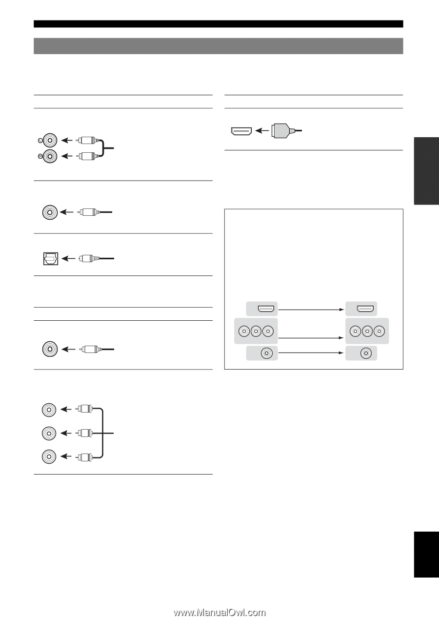
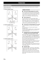
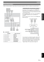
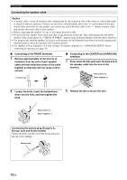
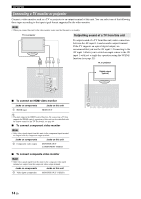
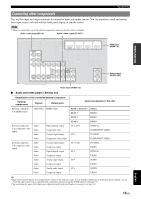
INTRODUCTION PREPARATION BASIC OPERATION Connections Information on jacks and cable plugs This unit has the following input and output jacks. Use jacks and cables appropriate for components that you are connecting. ■ Audio jacks ■ Video/audio jacks Jack and cables Description Jack and cables Description AUDIO jacks (white) L R AUDIO (red) COAXIAL jacks (orange) C COAXIAL OPTICAL jacks O OPTICAL To transmit conventional analog left and right audio signals. Use stereo pin cables. Connect red plugs to red jacks (R) and white plugs to white jacks (L). To transmit coaxial digital audio signals. Use pin cables for digital audio signals. To transmit optical digital audio signals. Use optical fiber cables for optical digital audio signals. HDMI jacks HDMI HDMI To transmit digital video and digital audio signals. Use HDMI cables. y • We recommend that you use a commercially available 19-pin HDMI cable no longer than 5 meters (16 feet) with the HDMI logo printed on it. • You can check the potential problem about the HDMI connection (see page 23). • You can check error information on HDMI connections (see page 23). A video signal input to this unit is output from the output terminals in MONITOR OUT for the same kind of signal as the input signal. For example, if a VCR with a composite output signal and a DVD player with a COMPONENT VIDEO output signal are connected, connect both VIDEO jack and COMPONENT VIDEO jack in MONITOR OUT to the video monitor. ■ Video jacks Jack and cables VIDEO jacks VIDEO V (yellow) Description To transmit conventional composite video signals. Use video pin cables. Input HDMI COMPONENT VIDEO PR PB Y VIDEO Output HDMI COMPONENT VIDEO PR PB Y VIDEO COMPONENT VIDEO jacks COMPONENT VIDEO PR PR (red) PB PB (blue) Y Y (green) To transmit component video signals that include luminance (Y), chrominance blue (PB) and chrominance red (PR) components. Use component video cables. ADVANCED OPERATION ADDITIONAL INFORMATION APPENDIX English 13 En
-
 1
1 -
2
-
3
-
4
-
5
-
6
-
7
-
8
-
9
-
10
-
11
-
 12
12 -
 13
13 -
 14
14 -
 15
15 -
 16
16 -
 17
17 -
 18
18 -
 19
19 -
 20
20 -
 21
21 -
 22
22 -
23
-
24
-
25
-
26
-
27
-
28
-
29
-
30
-
31
-
32
-
33
-
34
-
35
-
36
-
37
-
38
-
39
-
40
-
41
-
42
-
43
-
44
-
45
-
46
-
47
-
48
-
49
-
50
-
51
-
52
-
53
-
54
-
55
-
56
-
57
-
58
-
59
-
60
-
61
-
62
-
63
-
64
-
65
-
66
-
67
-
68
-
69
-
70
-
71
-
72
-
73
-
74
 |
 |