Yamaha YSP-600 Owner's Manual - Page 97
Installing this unit, Connecting external components to this unit, QUICK REFERENCE GUIDE
 |
View all Yamaha YSP-600 manuals
Add to My Manuals
Save this manual to your list of manuals |
Page 97 highlights
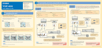
YSP-600 QUICK REFERENCE GUIDE Supplied accessories used for connections and operations in this guide s Audio pin cable (x1) s OSD* video pin cable (x1) s Optical cable (x1) s Digital audio pin cable (x1) s IntelliBeam microphone (x1) s Cardboard microphone stand (x1) s Demonstration DVD (x1) *OSD: On-Screen Display This quick reference guide explains steps to connect a TV and a DVD player/recorder to this unit and achieve the surround sound effects in a quick, easy manner. For detailed operation, refer to the Owner's Manual. 1 Installing this unit Decide where to install this unit. Install this unit where there are no objects such as furniture obstructing the path of sound beams. Otherwise, the desired surround sound efects may not be achieved. You may install this unit in parallel with the wall or in the corner. Install this unit in the exact center of the wall when it is measured from the left and right corners. Install this unit in the corner at a 40º to 50º angle from the adjacent walls. An object, such as furniture Front left channel Center channel Front right channel Surround left channel Surround right channel An object, such as furniture 40º to 50º Front left channel Center channel Front right channel Surround left channel Surround right channel Install this unit using a rack, etc. Depending on your installation environment, connections with external components (see "2 Connecting external components to this unit") can be done before installing this unit. We recommend that you temporarily place and arrange all components in order to decide which procedure must come first. For further information on installation, see page 13 in the Owner's Manual. The following is an example of installing this unit in a rack. 1 Place this unit in front of the rack. 2 Connect this unit to your 3 Install this unit in the TV and DVD player/recorder. rack. 4 Installation is completed. y Hint To enjoy better surround effects, place this unit on the upper shelf to keep it away from the floor. Note Be careful not to leave scratches on this unit or the rack. Printed in Malaysia WN77830 [En] 2 Connecting external components to this unit Connecting external components such as a TV or DVD player/recorder to this unit. Connect your TV or DVD player/recorder to this unit using appropriate cables as shown below. For further information on connecting other components, see pages 16 to 26 in the Owner's Manual. Connection example 1 This connection example shows a way to connect external components such as a TV or DVD player/recorder to this unit by using the supplied cable. You can enjoy the multi-channel audio from the DVD player/recorder and the analog/digital audio from the TV. Use the video pin cable supplied with your DVD player/recorder to make a video connection between your DVD player/recorder and TV. Connect cables in the following order. Supplied 1 Audio pin cable (Inputs the TV analog audio sounds to this unit) 2 OSD video pin cable (Displays the YSP-600 menu screen on the TV) 3 Optical cable (Inputs the TV digital audio sounds to this unit) 4 Digital audio pin cable (Inputs the DVD digital audio sounds to this unit) TV DVD player/recorder Video connection ANALOG AUDIO OUTPUT L R VIDEO INPUT 1 2 OPTICAL DIGITAL OUTPUT 1 2 3 COAXIAL DIGITAL OUTPUT 4 1. Pull out the cap. 2. Check the direction. Optical cable Pull out the cap before connecting the optical cable, and then check the direction to insert the cable. OUT DVD IN AUX HDMI L R VCR TV/STB SUBWOOFER VIDEO AUDIO INPUT OUT TV/STB AUX DVD SYSTEM OPTICAL COAXIAL CONNECTOR DIGITAL INPUT VCR TV/STB SUBWOOFER VIDEO AUDIO INPUT OUT TV/STB AUX OPTICAL DVD SYSTEM COAXIAL CONNECTOR DIGITAL INPUT Subwoofer System connection Audio connection YSP-600 To the AC wall outlet Do not plug the power supply cable into an AC wall outlet until all connections are complete. If a subwoofer is connected to this unit, turn on the power of your subwoofer and then carry out the AUTO SETUP procedure (see the backside) or select "SWFR" for "BASS OUT" in "SUBWOOFER SET" via MANUAL SETUP (see page 64 in the Owner's Manual). Note Check whether the digital audio output of your TV and DVD player/recorder is turned on. If you have connected external components, follow the steps on the backside to start the Continued AUTO SETUP procedure. on the back Connection example 2 This connection example shows a way to make the most of the capability of this unit. You can enjoy DVD audio and video with higher quality via the HDMI cable. In case your TV does not have a built-in digital satellite tuner, cable TV tuner, or digital airwave tuner, connect a digital satellite tuner, cable TV tuner, or digital airwave tuner via the HDMI cable. For details, see "Connections using HDMI cables" on page 18 and "Using the HDMI control feature" on page 57 in the Owner's Manual. Connect cables in the following order. 1 HDMI cable (sold separately) (Displays the DVD digital video on the TV) 2 OSD video pin cable (supplied) (Displays the YSP-600 menu screen on the TV) 3 Optical cable (supplied) (Inputs the TV digital audio sounds to this unit) 4 HDMI cable (sold separately) (Inputs the DVD digital audio/video signals to this unit) TV HDMI INPUT 1 (Sold separately) VIDEO INPUT 1 2 OPTICAL DIGITAL OUTPUT 2 3 DVD player/recorder 1. Pull out the cap. * If TV built-in tuner is used, connect the optical digital output jack on your TV to the TV/STB OPTICAL DIGITAL INPUT jack on this unit. HDMI OUTPUT 2. Check the direction. 4 (Sold separately) Optical cable Pull out the cap before connecting the optical cable, and then check the direction to insert the cable. OUT DVD IN AUX HDMI OUT DVD IN AUX HDMI L R VCR TV/STB SUBWOOFER VIDEO AUDIO INPUT OUT TV/STB AUX DVD SYSTEM OPTICAL COAXIAL CONNECTOR DIGITAL INPUT VCR TV/STB SUBWOOFER VIDEO AUDIO INPUT OUT TV/STB AUX OPTICAL DVD SYSTEM COAXIAL CONNECTOR DIGITAL INPUT Subwoofer System connection Audio connection YSP-600 To the AC wall outlet Do not plug the power supply cable into an AC wall outlet until all connections are complete. If a subwoofer is connected to this unit, turn on the power of your subwoofer and then carry out the AUTO SETUP procedure (see the backside) or select "SWFR" for "BASS OUT" in "SUBWOOFER SET" via MANUAL SETUP (see page 64 in the Owner's Manual). y Hint If you connect this unit to an HDMI control-compatible TV (except some models) via HDMI, you can use the remote control supplied with your TV to turn on or off the power, select the audio output component, and adjust the volume level of this unit. Note Check whether the digital audio output of your TV and DVD player/recorder is turned on. If you have connected external components, follow the steps on the backside to start the Continued AUTO SETUP procedure. on the back ©2008 All rights reserved.
-
 1
1 -
2
-
3
-
4
-
5
-
6
-
7
-
8
-
9
-
10
-
11
-
12
-
13
-
14
-
15
-
16
-
17
-
18
-
19
-
20
-
21
-
22
-
23
-
24
-
25
-
26
-
27
-
28
-
29
-
30
-
31
-
32
-
33
-
34
-
35
-
36
-
37
-
38
-
39
-
40
-
41
-
42
-
43
-
44
-
45
-
46
-
47
-
48
-
49
-
50
-
51
-
52
-
53
-
54
-
55
-
56
-
57
-
58
-
59
-
60
-
61
-
62
-
63
-
64
-
65
-
66
-
67
-
68
-
69
-
70
-
71
-
72
-
73
-
74
-
75
-
76
-
77
-
78
-
79
-
80
-
81
-
82
-
83
-
84
-
85
-
86
-
87
-
88
-
89
-
90
-
91
-
 92
92 -
 93
93 -
 94
94 -
 95
95 -
 96
96 -
 97
97 -
 98
98
 |
 |
