2006 BMW M6 Owner's Manual - Page 188
2006 BMW M6 Manual

Page 188 highlights
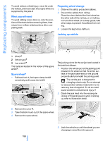
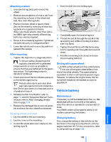
Replacing components Model with pressure gauge on hose* 9 Connecting hose for connecting compressor and sealant bottle or compressor and wheel Connector, cable and connecting hose are stored on underside of compressor. Using M Mobility System To repair a flat tire with the M Mobility System, proceed as follows: > Fill sealant into wheel, refer to page 186. 3 4 5 6 7 8 9 Connector and cable for lighter socket Mounting for sealing bottle Compressor On/Off switch Pressure gauge for indicating tire inflation pressure Screw on pressure gauge for reducing tire inflation pressure Connecting hose for connecting compressor and sealant bottle or compressor and wheel > Distribute sealant, refer to page 187. > Produce tire inflation pressure, refer to page 187. Filling sealant into wheel Strictly comply with the specified order, otherwise highly pressurized sealant could escape.< 1. Shake sealant bottle. 2. Screw hose 9 onto connection of sealant bottle. 3. For model with pressure gauge on hose: Make sure that screw 8 on pressure gauge is closed. 4. Screw dust cap off valve of defective wheel and screw filling hose 2 of sealant bottle onto valve. 5. Insert sealant bottle on compressor housing so that it is positioned upright. Connector, cable and connecting hose are stored in the compressor housing. Model with pressure gauge integrated in housing* 3 4 5 6 7 8 Connector and cable for lighter socket Mounting for sealing bottle Compressor On/Off switch Pressure gauge for indicating tire inflation pressure Button for reducing tire inflation pressure 6. Make sure that device is switched off, position 0. 7. Insert connector 3 into lighter socket in vehicle interior, refer to page 93. 186 Online Edition for Part No. 01 41 0 012 118 - © 02/06 BMW AG
-
 1
1 -
2
-
3
-
4
-
5
-
6
-
7
-
8
-
9
-
10
-
11
-
12
-
13
-
14
-
15
-
16
-
17
-
18
-
19
-
20
-
21
-
22
-
23
-
24
-
25
-
26
-
27
-
28
-
29
-
30
-
31
-
32
-
33
-
34
-
35
-
36
-
37
-
38
-
39
-
40
-
41
-
42
-
43
-
44
-
45
-
46
-
47
-
48
-
49
-
50
-
51
-
52
-
53
-
54
-
55
-
56
-
57
-
58
-
59
-
60
-
61
-
62
-
63
-
64
-
65
-
66
-
67
-
68
-
69
-
70
-
71
-
72
-
73
-
74
-
75
-
76
-
77
-
78
-
79
-
80
-
81
-
82
-
83
-
84
-
85
-
86
-
87
-
88
-
89
-
90
-
91
-
92
-
93
-
94
-
95
-
96
-
97
-
98
-
99
-
100
-
101
-
102
-
103
-
104
-
105
-
106
-
107
-
108
-
109
-
110
-
111
-
112
-
113
-
114
-
115
-
116
-
117
-
118
-
119
-
120
-
121
-
122
-
123
-
124
-
125
-
126
-
127
-
128
-
129
-
130
-
131
-
132
-
133
-
134
-
135
-
136
-
137
-
138
-
139
-
140
-
141
-
142
-
143
-
144
-
145
-
146
-
147
-
148
-
149
-
150
-
151
-
152
-
153
-
154
-
155
-
156
-
157
-
158
-
159
-
160
-
161
-
162
-
163
-
164
-
165
-
166
-
167
-
168
-
169
-
170
-
171
-
172
-
173
-
174
-
175
-
176
-
177
-
178
-
179
-
180
-
181
-
182
-
 183
183 -
 184
184 -
 185
185 -
 186
186 -
 187
187 -
 188
188 -
 189
189 -
 190
190 -
 191
191 -
 192
192 -
 193
193 -
194
-
195
-
196
-
197
-
198
-
199
-
200
-
201
-
202
-
203
-
204
-
205
-
206
-
207
-
208
-
209
-
210
-
211
-
212
-
213
-
214
-
215
-
216
-
217
-
218
-
219
-
220
-
221
-
222
-
223
-
224
-
225
-
226
-
227
 |
 |
