2007 BMW M5 Owner's Manual - Page 216
2007 BMW M5 Manual

Page 216 highlights
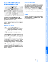
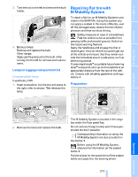
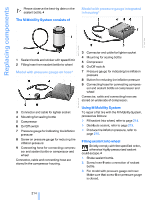
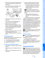
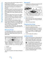
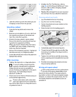
Replacing components Please observe the best-by date on the sealant bottle.< Model with pressure gauge integrated in housing* The M Mobility System consists of 3 1 2 Sealant bottle and sticker with speed limit Filling hose from sealant bottle to wheel 4 5 6 7 8 9 Connector and cable for lighter socket Mounting for sealing bottle Compressor On/Off switch Pressure gauge for indicating tire inflation pressure Button for reducing tire inflation pressure Connecting hose for connecting compressor and sealant bottle or compressor and wheel Model with pressure gauge on hose* Connector, cable and connecting hose are stored on underside of compressor. Using M Mobility System 3 4 5 6 7 8 9 Connector and cable for lighter socket Mounting for sealing bottle Compressor On/Off switch Pressure gauge for indicating tire inflation pressure Screw on pressure gauge for reducing tire inflation pressure Connecting hose for connecting compressor and sealant bottle or compressor and wheel To repair a flat tire with the M Mobility System, proceed as follows: > Fill sealant into wheel, refer to page 214. > Distribute sealant, refer to page 215. > Produce tire inflation pressure, refer to page 215. Filling sealant into wheel Strictly comply with the specified order, otherwise highly pressurized sealant could escape.< 1. Shake sealant bottle. 2. Screw hose 9 onto connection of sealant bottle. 3. For model with pressure gauge on hose: Make sure that screw 8 on pressure gauge is closed. Connector, cable and connecting hose are stored in the compressor housing. 214 Online Edition for Part no. 01 41 0 013 310 - © 02/07 BMW AG
-
 1
1 -
2
-
3
-
4
-
5
-
6
-
7
-
8
-
9
-
10
-
11
-
12
-
13
-
14
-
15
-
16
-
17
-
18
-
19
-
20
-
21
-
22
-
23
-
24
-
25
-
26
-
27
-
28
-
29
-
30
-
31
-
32
-
33
-
34
-
35
-
36
-
37
-
38
-
39
-
40
-
41
-
42
-
43
-
44
-
45
-
46
-
47
-
48
-
49
-
50
-
51
-
52
-
53
-
54
-
55
-
56
-
57
-
58
-
59
-
60
-
61
-
62
-
63
-
64
-
65
-
66
-
67
-
68
-
69
-
70
-
71
-
72
-
73
-
74
-
75
-
76
-
77
-
78
-
79
-
80
-
81
-
82
-
83
-
84
-
85
-
86
-
87
-
88
-
89
-
90
-
91
-
92
-
93
-
94
-
95
-
96
-
97
-
98
-
99
-
100
-
101
-
102
-
103
-
104
-
105
-
106
-
107
-
108
-
109
-
110
-
111
-
112
-
113
-
114
-
115
-
116
-
117
-
118
-
119
-
120
-
121
-
122
-
123
-
124
-
125
-
126
-
127
-
128
-
129
-
130
-
131
-
132
-
133
-
134
-
135
-
136
-
137
-
138
-
139
-
140
-
141
-
142
-
143
-
144
-
145
-
146
-
147
-
148
-
149
-
150
-
151
-
152
-
153
-
154
-
155
-
156
-
157
-
158
-
159
-
160
-
161
-
162
-
163
-
164
-
165
-
166
-
167
-
168
-
169
-
170
-
171
-
172
-
173
-
174
-
175
-
176
-
177
-
178
-
179
-
180
-
181
-
182
-
183
-
184
-
185
-
186
-
187
-
188
-
189
-
190
-
191
-
192
-
193
-
194
-
195
-
196
-
197
-
198
-
199
-
200
-
201
-
202
-
203
-
204
-
205
-
206
-
207
-
208
-
209
-
210
-
 211
211 -
 212
212 -
 213
213 -
 214
214 -
 215
215 -
 216
216 -
 217
217 -
 218
218 -
 219
219 -
 220
220 -
 221
221 -
222
-
223
-
224
-
225
-
226
-
227
-
228
-
229
-
230
-
231
-
232
-
233
-
234
-
235
-
236
-
237
-
238
-
239
-
240
-
241
-
242
-
243
-
244
-
245
-
246
-
247
-
248
-
249
-
250
-
251
-
252
-
253
-
254
-
255
-
256
 |
 |
