2015 Ducati Superbike 1299 Panigale S Owners Manual - Page 330
2015 Ducati Superbike 1299 Panigale S Manual

Page 330 highlights
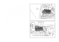
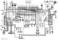
51) 52) 53) 54) 55) 56) 57) 58) 59) 60) 61) 62) 63) 64) 65) 66) 67) 68) 69) Main vertical injector Top vertical injector Horizontal ETV drive Vertical ETV drive Secondary air actuator ABS control unit Left-hand switch Front suspension - rebound - Stepper B Front suspension - compression - Stepper A Horn Inertial platform Front left turn indicator Instrument panel UP/DOWN auxiliary switch Headlight Front right turn indicator Steering damper Smart EC control unit Purge valve Y Yellow R Red Lb Light blue Gr Gray G Green Bn Brown O Orange P Pink Note The electric system wiring diagram is at the end of this manual. Wire color coding B Blue W White V Violet Bk Black 328
-
 1
1 -
2
-
3
-
4
-
5
-
6
-
7
-
8
-
9
-
10
-
11
-
12
-
13
-
14
-
15
-
16
-
17
-
18
-
19
-
20
-
21
-
22
-
23
-
24
-
25
-
26
-
27
-
28
-
29
-
30
-
31
-
32
-
33
-
34
-
35
-
36
-
37
-
38
-
39
-
40
-
41
-
42
-
43
-
44
-
45
-
46
-
47
-
48
-
49
-
50
-
51
-
52
-
53
-
54
-
55
-
56
-
57
-
58
-
59
-
60
-
61
-
62
-
63
-
64
-
65
-
66
-
67
-
68
-
69
-
70
-
71
-
72
-
73
-
74
-
75
-
76
-
77
-
78
-
79
-
80
-
81
-
82
-
83
-
84
-
85
-
86
-
87
-
88
-
89
-
90
-
91
-
92
-
93
-
94
-
95
-
96
-
97
-
98
-
99
-
100
-
101
-
102
-
103
-
104
-
105
-
106
-
107
-
108
-
109
-
110
-
111
-
112
-
113
-
114
-
115
-
116
-
117
-
118
-
119
-
120
-
121
-
122
-
123
-
124
-
125
-
126
-
127
-
128
-
129
-
130
-
131
-
132
-
133
-
134
-
135
-
136
-
137
-
138
-
139
-
140
-
141
-
142
-
143
-
144
-
145
-
146
-
147
-
148
-
149
-
150
-
151
-
152
-
153
-
154
-
155
-
156
-
157
-
158
-
159
-
160
-
161
-
162
-
163
-
164
-
165
-
166
-
167
-
168
-
169
-
170
-
171
-
172
-
173
-
174
-
175
-
176
-
177
-
178
-
179
-
180
-
181
-
182
-
183
-
184
-
185
-
186
-
187
-
188
-
189
-
190
-
191
-
192
-
193
-
194
-
195
-
196
-
197
-
198
-
199
-
200
-
201
-
202
-
203
-
204
-
205
-
206
-
207
-
208
-
209
-
210
-
211
-
212
-
213
-
214
-
215
-
216
-
217
-
218
-
219
-
220
-
221
-
222
-
223
-
224
-
225
-
226
-
227
-
228
-
229
-
230
-
231
-
232
-
233
-
234
-
235
-
236
-
237
-
238
-
239
-
240
-
241
-
242
-
243
-
244
-
245
-
246
-
247
-
248
-
249
-
250
-
251
-
252
-
253
-
254
-
255
-
256
-
257
-
258
-
259
-
260
-
261
-
262
-
263
-
264
-
265
-
266
-
267
-
268
-
269
-
270
-
271
-
272
-
273
-
274
-
275
-
276
-
277
-
278
-
279
-
280
-
281
-
282
-
283
-
284
-
285
-
286
-
287
-
288
-
289
-
290
-
291
-
292
-
293
-
294
-
295
-
296
-
297
-
298
-
299
-
300
-
301
-
302
-
303
-
304
-
305
-
306
-
307
-
308
-
309
-
310
-
311
-
312
-
313
-
314
-
315
-
316
-
317
-
318
-
319
-
320
-
321
-
322
-
323
-
324
-
 325
325 -
 326
326 -
 327
327 -
 328
328 -
 329
329 -
 330
330 -
 331
331 -
 332
332 -
 333
333 -
 334
334
 |
 |
51)
Main vertical injector
52)
Top vertical injector
53)
Horizontal ETV drive
54)
Vertical ETV drive
55)
Secondary air actuator
56)
ABS control unit
57)
Left-hand switch
58)
Front suspension - rebound - Stepper B
59)
Front suspension - compression - Stepper A
60)
Horn
61)
Inertial platform
62)
Front left turn indicator
63)
Instrument panel
64)
UP/DOWN auxiliary switch
65)
Headlight
66)
Front right turn indicator
67)
Steering damper
68)
Smart EC control unit
69)
Purge valve
Wire color coding
B Blue
W White
V Violet
Bk Black
Y Yellow
R Red
Lb Light blue
Gr Gray
G Green
Bn Brown
O Orange
P Pink
Note
The electric system wiring diagram is at the end
of this manual.
328