3Com 3C16476A User Guide - Page 49
Port Mirroring
 |
UPC - 662705475448
View all 3Com 3C16476A manuals
Add to My Manuals
Save this manual to your list of manuals |
Page 49 highlights
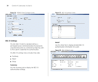
Figure 46 Spanning Tree Detail Screen Configuring Port Settings 49 device with the lowest MAC address will then become the root device. If you modify any of these settings, click Apply to save your changes. Figure 47 Spanning Tree Setup Screen Setup Use the Setup tab to configure the spanning tree settings for each port. The following options are available: ■ Status - Enables and disables spanning tree for the port. ■ Edged Port - Enables and disables edged port for the port. ■ Link Type - Choose between Point-to-Point, Shared, or Auto for the link type. ■ Path Cost - The path cost is used to determine the best path between devices. The path cost method is used to determine the range of values that can be assigned to each interface. ■ Port Priority - Used in selecting the root device, root port, and designated port. The device with the highest priority becomes the STA root device. However, if all devices have the same priority, the Port Mirroring The Switch allows you to monitor traffic going in and out of a particular port. For traffic monitoring to work, you need to attach a network analyzer to one port and use it to monitor the traffic of other ports in the stack. To set up traffic monitoring, you need to set an analysis port (the port that is connected to the analyzer), and a monitor port (the port that is to be monitored). Once the pair is defined, and you enable traffic monitoring, the Switch takes all the traffic going in and out of the monitor port and copies it to the analysis port. CAUTION: The analyzer port should have a higher bandwidth than the mirror port. Otherwise, the Switch may not be able to copy all traffic effectively during periods of high traffic.
-
 1
1 -
2
-
3
-
4
-
5
-
6
-
7
-
8
-
9
-
10
-
11
-
12
-
13
-
14
-
15
-
16
-
17
-
18
-
19
-
20
-
21
-
22
-
23
-
24
-
25
-
26
-
27
-
28
-
29
-
30
-
31
-
32
-
33
-
34
-
35
-
36
-
37
-
38
-
39
-
40
-
41
-
42
-
43
-
 44
44 -
 45
45 -
 46
46 -
 47
47 -
 48
48 -
 49
49 -
 50
50 -
 51
51 -
 52
52 -
 53
53 -
 54
54 -
55
-
56
-
57
-
58
-
59
-
60
-
61
-
62
-
63
-
64
-
65
-
66
-
67
-
68
-
69
-
70
-
71
-
72
-
73
-
74
-
75
-
76
-
77
-
78
-
79
 |
 |
