Acer Aspire 9500 Service Guide - Page 65
Disassemble the Cables, Antenna and LCD Module
 |
View all Acer Aspire 9500 manuals
Add to My Manuals
Save this manual to your list of manuals |
Page 65 highlights
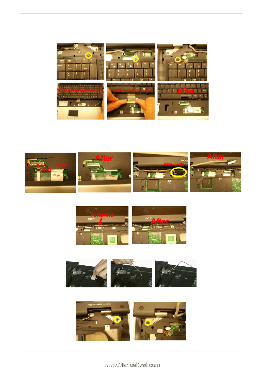
6. Remove the three screws at the top of the keyboard. 7. Lift up the keyboard and hold it up and slightly forward to allow access to the keyboard connector. 8. Pull up on the keyboard connector pull-tab to disconnect the keyboard connector from the system board. Disassemble the Cables, Antenna and LCD Module 1. Disconnect the touchpad cable and CD-Player cable. 2. Disconnect the wire cable from the board. 3. Disconnect the Antenna cable. 4. Tear the tape then pull the antenna cables from the routing channels. 5. Loosen the two screws on each side as shown here. 60 Chapter 3
-
 1
1 -
2
-
3
-
4
-
5
-
6
-
7
-
8
-
9
-
10
-
11
-
12
-
13
-
14
-
15
-
16
-
17
-
18
-
19
-
20
-
21
-
22
-
23
-
24
-
25
-
26
-
27
-
28
-
29
-
30
-
31
-
32
-
33
-
34
-
35
-
36
-
37
-
38
-
39
-
40
-
41
-
42
-
43
-
44
-
45
-
46
-
47
-
48
-
49
-
50
-
51
-
52
-
53
-
54
-
55
-
56
-
57
-
58
-
59
-
 60
60 -
 61
61 -
 62
62 -
 63
63 -
 64
64 -
 65
65 -
 66
66 -
 67
67 -
 68
68 -
 69
69 -
 70
70 -
71
-
72
-
73
-
74
-
75
-
76
-
77
-
78
-
79
-
80
-
81
-
82
-
83
-
84
-
85
-
86
-
87
-
88
-
89
-
90
-
91
-
92
-
93
-
94
-
95
-
96
-
97
-
98
-
99
-
100
-
101
-
102
-
103
-
104
-
105
-
106
-
107
-
108
-
109
-
110
-
111
-
112
-
113
-
114
-
115
-
116
-
117
-
118
-
119
-
120
-
121
-
122
-
123
-
124
-
125
-
126
-
127
-
128
-
129
 |
 |
60
Chapter 3
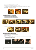
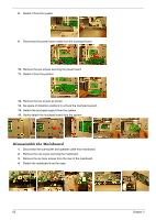
6.
Remove the three screws at the top of the keyboard.
7.
Lift up the keyboard and hold it up and slightly forward to allow access to the keyboard connector.
8.
Pull up on the keyboard connector pull-tab to disconnect the keyboard connector from the system board.
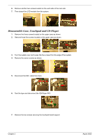
Disassemble the Cables, Antenna and LCD Module
1.
Disconnect the touchpad cable and CD-Player cable.
2.
Disconnect the wire cable from the board.
3.
Disconnect the Antenna cable.
4.
Tear the tape then pull the antenna cables from the routing channels.
5.
Loosen the two screws on each side as shown here.