Asus AP1710-E1 AP1710-E1 English version manual - Page 104
Internal connectors
 |
View all Asus AP1710-E1 manuals
Add to My Manuals
Save this manual to your list of manuals |
Page 104 highlights
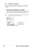
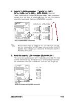
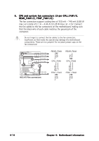
4.3 Internal connectors This section describes and illustrates the connectors on the motherboard. See section "1.4 Rear panel features" for the description of rear panel connectors. 1 . Floppy disk drive connector (34-1 pin FLOPPY) This connector is for the provided floppy disk drive (FDD) signal cable. Insert one end of the cable to this connector, then connect the other end to the signal connector at the back of the floppy disk drive. Pin 5 on the connector is removed to prevent incorrect cable connection when using a FDD cable with a covered Pin 5. NCLV-D FLOPPY PIN 1 NOTE: Orient the red markings on the floppy ribbon cable to PIN 1. NCLV-D Floppy disk drive connector 4-10 Chapter 4: Motherboard information
-
 1
1 -
2
-
3
-
4
-
5
-
6
-
7
-
8
-
9
-
10
-
11
-
12
-
13
-
14
-
15
-
16
-
17
-
18
-
19
-
20
-
21
-
22
-
23
-
24
-
25
-
26
-
27
-
28
-
29
-
30
-
31
-
32
-
33
-
34
-
35
-
36
-
37
-
38
-
39
-
40
-
41
-
42
-
43
-
44
-
45
-
46
-
47
-
48
-
49
-
50
-
51
-
52
-
53
-
54
-
55
-
56
-
57
-
58
-
59
-
60
-
61
-
62
-
63
-
64
-
65
-
66
-
67
-
68
-
69
-
70
-
71
-
72
-
73
-
74
-
75
-
76
-
77
-
78
-
79
-
80
-
81
-
82
-
83
-
84
-
85
-
86
-
87
-
88
-
89
-
90
-
91
-
92
-
93
-
94
-
95
-
96
-
97
-
98
-
 99
99 -
 100
100 -
 101
101 -
 102
102 -
 103
103 -
 104
104 -
 105
105 -
 106
106 -
 107
107 -
 108
108 -
 109
109 -
110
-
111
-
112
-
113
-
114
-
115
-
116
-
117
-
118
-
119
-
120
-
121
-
122
-
123
-
124
-
125
-
126
-
127
-
128
-
129
-
130
-
131
-
132
-
133
-
134
-
135
-
136
-
137
-
138
-
139
-
140
-
141
-
142
-
143
-
144
-
145
-
146
-
147
-
148
-
149
-
150
-
151
-
152
-
153
-
154
-
155
-
156
-
157
-
158
 |
 |

Chapter 4:
Motherboard information
Chapter 4:
Motherboard information
Chapter 4:
Motherboard information
Chapter 4:
Motherboard information
Chapter 4:
Motherboard information
4-10
4-10
4-10
4-10
4-10
4.3
Internal connectors
This section describes and illustrates the connectors on the motherboard.
See section “1.4 Rear panel features” for the description of rear panel
connectors.
Pin 5 on the connector is removed to prevent incorrect cable connection
when using a FDD cable with a covered Pin 5.
NCLV-D
NOTE:
Orient the red markings on
the floppy ribbon cable to PIN 1.
NCLV-D Floppy disk drive connector
PIN 1
FLOPPY
1.
1.
1.
1.
1.
Floppy disk drive connector (34-1 pin FLOPPY)
Floppy disk drive connector (34-1 pin FLOPPY)
Floppy disk drive connector (34-1 pin FLOPPY)
Floppy disk drive connector (34-1 pin FLOPPY)
Floppy disk drive connector (34-1 pin FLOPPY)
This connector is for the provided floppy disk drive (FDD) signal cable.
Insert one end of the cable to this connector, then connect the other
end to the signal connector at the back of the floppy disk drive.