Asus AP1710-E1 AP1710-E1 English version manual - Page 75
Insert the I/O board
 |
View all Asus AP1710-E1 manuals
Add to My Manuals
Save this manual to your list of manuals |
Page 75 highlights
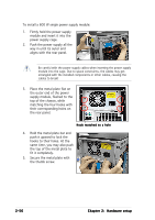
To install the front I/O board: 1. Place the I/O board in the bracket, component side up. Secure the front I/O board to the bracket with a screw. 2. Position the I/O board into the bay with the component side to the left (close to the HDDs). Connect the I/O cables to the connectors on the back of the I/O board. 3. Insert the I/O board into the bay until the bracket fits the front edge of the bay. 4. Secure the I/O board bracket with a screw. USB 2.0 connector ASUS AP1710-E1 2-51
-
 1
1 -
2
-
3
-
4
-
5
-
6
-
7
-
8
-
9
-
10
-
11
-
12
-
13
-
14
-
15
-
16
-
17
-
18
-
19
-
20
-
21
-
22
-
23
-
24
-
25
-
26
-
27
-
28
-
29
-
30
-
31
-
32
-
33
-
34
-
35
-
36
-
37
-
38
-
39
-
40
-
41
-
42
-
43
-
44
-
45
-
46
-
47
-
48
-
49
-
50
-
51
-
52
-
53
-
54
-
55
-
56
-
57
-
58
-
59
-
60
-
61
-
62
-
63
-
64
-
65
-
66
-
67
-
68
-
69
-
 70
70 -
 71
71 -
 72
72 -
 73
73 -
 74
74 -
 75
75 -
 76
76 -
 77
77 -
 78
78 -
 79
79 -
 80
80 -
81
-
82
-
83
-
84
-
85
-
86
-
87
-
88
-
89
-
90
-
91
-
92
-
93
-
94
-
95
-
96
-
97
-
98
-
99
-
100
-
101
-
102
-
103
-
104
-
105
-
106
-
107
-
108
-
109
-
110
-
111
-
112
-
113
-
114
-
115
-
116
-
117
-
118
-
119
-
120
-
121
-
122
-
123
-
124
-
125
-
126
-
127
-
128
-
129
-
130
-
131
-
132
-
133
-
134
-
135
-
136
-
137
-
138
-
139
-
140
-
141
-
142
-
143
-
144
-
145
-
146
-
147
-
148
-
149
-
150
-
151
-
152
-
153
-
154
-
155
-
156
-
157
-
158
 |
 |

2-51
2-51
2-51
2-51
2-51
ASUS AP1710-E1
ASUS AP1710-E1
ASUS AP1710-E1
ASUS AP1710-E1
ASUS AP1710-E1
To install the front I/O board:
1.
Place the I/O board in the
bracket, component side up.
Secure the front I/O board to
the bracket with a screw.
2.
Position the I/O board into the
bay with the component side to
the left (close to the HDDs).
Connect the I/O cables to the
connectors on the back of the
I/O board.
3.
Insert the I/O board
into the
bay until the
bracket fits the
front edge of the bay.
4.
Secure the I/O board bracket
with a screw.
USB 2.0 connector
USB 2.0 connector
USB 2.0 connector
USB 2.0 connector
USB 2.0 connector